| Electrical Communication is a free textbook on the basics of communication technology. See the editorial for more information.... |

|
Home  Radio Wave Propagation and Antennas Antennas for Amplitude-Modulation Broadcast Stations Radio Wave Propagation and Antennas Antennas for Amplitude-Modulation Broadcast Stations |
|||||||||


|
  |
||||||||
Antennas for Amplitude-Modulation Broadcast StationsThese antennas operate at fixed frequencies within the band 550 to 1600 kilocycles. In general, they are designed to supply a strong signal to the area adjacent to the transmitter, transmission being largely by the surface-wave component of the ground wave. Usually, the coverage of the area is merely attributed to the ground wave.16 The antenna radiates the carrier and two sidebands (page 489), requiring about 5000 cycles each side of the carrier. The carrier frequency is used in calculations. Non-directional Antennas for A-M Broadcast Station. Because ground-wave propagation is desired, the antennas usually are vertical and radiate vertically polarized waves. In general, it is desired that sky-wave radiation be a minimum. In daytime sky-wave transmission at 550 to 1600 kilocycles is negligible because of ionospheric absorption (page 445), but, at night, reflection from the ionosphere occurs, and one broadcast station may seriously interfere with another station, perhaps a thousand miles away and operating on the same frequency or an adjacent frequency. In the design of a broadcast antenna, it is, therefore, necessary to consider the radiation both in the horizontal plane, represented by the surface of the earth, and in vertical planes. If the antenna system is to be non-directional, a single vertical antenna is used. Neglecting losses, the radiation along the surface of the earth will be uniform (page 444), giving a circular pattern. The method of computing the field intensity is discussed on page 453. The shape of the radiation pattern in a vertical plane depends on the antenna height, the patterns for several heights being shown in Fig. 24. Although an antenna height of about 0.62λ theoretically gives the strongest ground-wave signal,40 it will be noted that a lobe has developed at about 60° with the horizontal. Such a lobe causes undesired high-angle sky-wave radiation that wastes power and may cause distant interference. When all factors are considered, a straight vertical antenna about 0.53λ has been found to make an excellent radiator.41 At the lower end of the broadcast band, an antenna this high is, physically, a sizable and expensive structure, and, although such towers are used, they are often a smaller fraction of a wavelength.
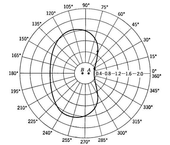
Many investigations have been made regarding height and shape of broadcast antennas, and the ground systems to be used with them. For many broadcast purposes an antenna of height about 0.25λ or even less, with a good ground system, has been shown42 to be satisfactory. A good ground system for a vertical antenna often consists of about 120 heavy copper wires, each about 0.25λ to 0.5λ long, and buried at a depth of several inches so that they extend radially from the base of the antenna. Directional Antennas for A-M Broadcast Stations. Sometimes it is necessary to use a directional antenna system with a broadcast station. For instance, sometimes the geographical distribution of the population is such that this is desirable; or perhaps it is necessary to "protect" the service area of a distant station by designing the radiation pattern so that the signal sent toward that station is not too strong. Such directional antenna systems usually consist of two or more vertical antennas located a fraction of a wavelength apart and driven by the same transmitter. For explaining the basic principle of operation, a two-element array will be considered. The design of a directional broadcast antenna system which will produce a given radiation pattern is a cut-and-try procedure. Thus, suppose that, after a careful study is made of all factors, an antenna radiation pattern such as Fig. 25 is selected. References 6 and 43 to 46 present many patterns and the means of producing them. Assume that an investigation indicates that to obtain a pattern such as Fig. 25 the two towers should be spaced 135° apart (one wavelength equals 360°), that the current in antenna B should lag that in A by 50°, and that the current in antenna B should be 0.7 that in A. These data will now be checked.
From Fig. 26 it is evident that radiation from antenna B must travel a distance S cosθ farther than the radiation from antenna A to reach some distant point. Using the angle θ = 30° as an illustration, S cos 30° = 135° x 0.866 = 117°. But the signal from antenna B is radiated 50° behind that from A\ hence at the distant point under consideration the signal from antenna B arrives 117° + 50° = 167° behind the signal from A. Thus, the total signal strength relative to A alone at an angle of 30° is the sum of two vectors, the first is assumed to be unity in magnitude and to be the reference vector, and the second is assumed to be 0.7 in magnitude (IB = 0.7 IA) and lags 167°. The signal strength at the distant point relative to that produced by antenna A alone is
This value is then plotted as indicated in Fig. 25, and other values are calculated to give the complete radiation pattern. An equation for the relative radiation compared to that due to antenna A in a horizontal plane at the surface of the earth at various bearing, or azimuth, angles θ, measured with respect to a line joining the antennas as shown in Fig. 26, readily follows from the preceding reasoning. This equation is Relative field strength at angle θ =
where k is the ratio of current in antenna B to that in A, α is the angle by which the current in antenna B lags that in A, S is the spacing in degrees, and θ is as previously noted. Thus, at 60°, the array previously considered produces a relative field strength of
This is found to fall on the curve of Fig. 25. The calculations just given are for the relative radiation only, compared to antenna A that is assumed to give unit radiation. If the actual field strength at any angle is desired, it can be computed for antenna A alone from equations 6, 7, or 8 and as discussed in the paragraph just following these equations. The radiation for antenna A alone, multiplied by the factors at the various angles from Fig. 25, will give a radiation pattern for the antennas in millivolts per meter, or other units used. Thus far, only the radiation, due to the two antennas, in a horizontal plane at the surface of the earth has been considered. Often, it is desired to know the radiation at various angles and in various vertical planes, so that the signal strength at some distant point via the sky-wave path can be determined.16 For this purpose, the following equation is often used41,44 Relative field strength =
In this equation φ is the angle in the vertical plane at which the radiation is to be computed and is measured with respect to the horizontal, H is the height of each of the two identical antennas in degrees, and all other values are as previously explained. Thus, suppose the height of each of the antennas previously considered is 65°, or less than one-fourth wavelength (90°), and the radiation along the horizontal (θ = 0°) at an angle of 60° with respect to the line of the towers is desired. Then, from equation 16,
At a zenith angle of 30° with respect to the horizon, and at an azimuth angle of 30° with respect to a line joining the two towers, the relative radiation will be from equation 16,
Antenna patterns can be determined by mechanical and electrical devices.47,48,49 The preceding discussion was for directional antenna arrays of two vertical towers. Sometimes, more than two towers are used. Information on such arrays can be found in the references already listed, particularly in reference 46. Directional Antennas for F-M Broadcast Stations. From the standpoint of size and shape, antennas used in frequency-modulation broadcasting differ greatly from those used in amplitude modulation. Among the reasons are first, the frequency is about 100 times greater, making possible antennas with small dimensions; second, horizontal polarization is used with frequency modulation instead of vertical polarization as in amplitude modulation; third, because there is less tendency for frequency-modulation stations to interfere and because transmission by sky wave does not usually occur at the high frequencies assigned, antenna systems that are horizontally directional are employed only to a limited extent. The antennas used in amplitude-modulation broadcast systems are almost always vertical towers, one being but little different from another. In frequency-modulation on the other hand, many shapes are used for the radiators.
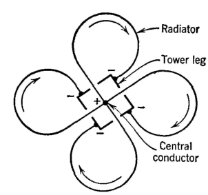
The configuration of the radiators of a typical antenna used in frequency-modulation broadcast is shown in Fig. 27. The loops are conductors of large diameter and are connected as indicated, the tower lags in parallel feeding one end of the loops, and a conductor at the center feeding the other end. Each loop conducts current as indicated by the arrows and is a radiator. As many as eight elements, such as shown in Fig. 27, are sometimes "stacked" into an array.50
|
|||||||||
| Home Radio Wave Propagation and Antennas Antennas for Amplitude-Modulation Broadcast Stations |
|
||||||||


Last Update: 2011-05-18