| Electrical Communication is a free textbook on the basics of communication technology. See the editorial for more information.... |

|
Home  Radio Wave Propagation and Antennas Driving-Point Impedance of Periodic Antennas Radio Wave Propagation and Antennas Driving-Point Impedance of Periodic Antennas |
|||||||


|
  |
||||||
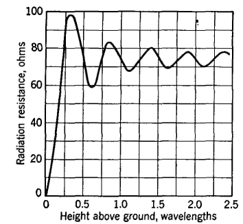
Driving-Point Impedance of Periodic AntennasAs shown in Fig. 11 an antenna is an electric circuit composed of resistance, inductance, and capacitance, and the voltage applied across its input terminals divided by the current that flows into these terminals is a measure of the driving-point impedance, self-impedance, or input impedance, as it is often called.51 As explained on page 460, for periodic antennas this impedance varies with the frequency of the applied voltage. The reason that the input impedance varies is evident from Fig. 12. From the theory of standing (stationary) waves, the input currents that voltages of different frequencies will produce will vary in both magnitude and phase, and hence the input, or driving-point, impedance will vary. It is possible to predict the input impedance of antennas of various types from theoretical consideration,3,44 but in practice, if the impedance must be known, bridge measurements are usually made on the actual antenna. As will be seen in the chapter that follows, the reactive component of the driving-point impedance is either ignored or canceled out with opposite reactance at the point where the antenna is driven. Of interest is the antenna resistance, defined34 as "the quotient of the power supplied to the entire antenna circuit by the square of the effective antenna current referred to a specified point." Antenna resistance includes34 radiation resistance, ground resistance, radio frequency resistance of conductors in the antenna circuit, equivalent resistance due to corona, eddy currents, insulator leakage, and dielectric power loss. In antenna design, of much importance is the radiation resistance, defined34 as "the quotient of the power radiated by an antenna by the square of the effective antenna current referred to a specified point." The radiation efficiency can be determined if the antenna resistance and radiation resistance are known. Radiation efficiency is defined34 as "the ratio of the power radiated to the total power supplied to the antenna at a given frequency." The theoretical radiation resistance of a half-wave antenna in free space and driven at center is 73 ohms. The radiation resistance of the horizontal half-wave antenna is affected by its position above the earth as indicated in Fig. 28.
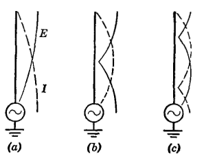
The input impedance of a typical vertical antenna for amplitude-modulation broadcast service is shown in Fig. 29. This antenna has zero reactance and hence is said to be resonant at frequencies of 0.685, 1.070, and 1.715 megacycles. At 0,685 megacycles the resistance is about
35 ohms. This is the natural frequency, defined34 as the "lowest resonant frequency obtained without added inductance or capacitance."' At 0.685 megacycles, the antenna functions as a grounded quarter-wave antenna with voltage and current distribution as shown in Fig. 30(a). At 1.070 megacycles, the driving point input impedance is 310 ohms resistance, the antenna is operating in resonance as a half-wave antenna fed at the end, and the voltage and current distribution are as shown in Fig. 30(b). At 1.715 megacycles the antenna of Fig. 29 is resonant, operation is as a three-quarter wave antenna, and the impedance is 20 ohms resistance. The voltage and current are distributed as in Fig. 30(c). An antenna does not have to be driven at a resonant frequency; however, the frequency at which it is driven affects the shape of the radiation pattern.
|
|||||||
| Home Radio Wave Propagation and Antennas Driving-Point Impedance of Periodic Antennas |
|
||||||

Last Update: 2011-05-30