| Electrical Communication is a free textbook on the basics of communication technology. See the editorial for more information.... |

|
Home  Radio Wave Propagation and Antennas The Rhombic Antenna Radio Wave Propagation and Antennas The Rhombic Antenna |
|||||||||||||


|
  |
||||||||||||
The Rhombic AntennaThe rhombic antenna53,54,55 is extensively used in both transmitting and receiving in short-wave, high-frequency, radio telephone and telegraph systems for point-to-point communication. It is defined34 as "an antenna composed of long-wire radiators comprising the sides of a rhombus." These conductors often are several wavelengths long and are terminated in an impedance at the "distant" end much like a transmission line so that no wave reflection exists on them. To determine the radiation pattern from a rhombic antenna the radiation from a single terminated wire must first be investigated.
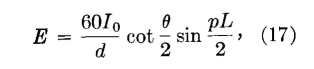
The radiation pattern from a long wire in free space is6
where E is the field strength in volts per meter, I0 is current input to the wire in amperes, d is the distance in meters, θ is the angle with respect to the axis of the wire, L is the wire length in wavelengths, and p = (2π/λ)(l - cos θ). Neglecting the minor lobes, Fig. 31 gives the free-space radiation pattern. The angle θ can be found
from Fig. 32, where θ = (90 - φ). This curve shows that the angle of maximum radiation is almost independent of the length of the wire for wire lengths of over several wavelengths, a very important point as will be explained later. Before continuing the discussion of the rhombic antenna, two other antennas should be considered.
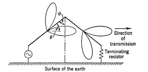
A tilted-wire antenna can be arranged as in Fig. 33. This simple structure is useful at the upper end of the high-frequency band. By the proper selection of wire length and angle φ, the antenna can be designed37 so that two of the lobes combine for directional transmission and so that the other two largely cancel. A non-resonant Vee antenna is arranged as shown in Fig. 34. The two wires are horizontal above the earth. For the proper wire length and angles, a highly directional antenna is obtained. The wires are several wavelengths long and terminated so that no reflection occurs.
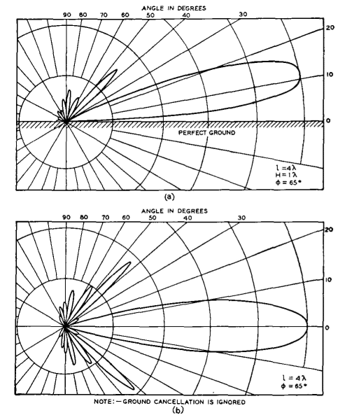
Horizontal rhombic antennas are shown in Fig. 35, and also in Fig. 20 of Chapter 13. This is one of the most satisfactory of- all types of directional antennas. The relative radiations in vertical and horizontal planes are shown in Fig. 36 for a typical rhombic antenna composed of wires each 4λ in length, held horizontally one wavelength above the earth, and with φ = 65° (see Fig. 32). The radiation of each wire, as indicated by the lobes in Fig. 35, combine to give the patterns of Fig. 36. The horizontal rhombic antenna requires no connection to ground, is non-resonant, and will operate well over a considerable band of frequencies because the angle φ of Fig. 32 varies but little with wavelength. This antenna is low in first cost, easy to maintain, and can be designed to meet a variety of operating conditions. It is important to note that it sends and receives best at some vertical angle with the surface of the earth. This angle can be varied by proper design. This adapts the horizontal rhombic antenna to sky-wave transmission and reception at high frequencies.
|
|||||||||||||
| Home Radio Wave Propagation and Antennas The Rhombic Antenna |
|
||||||||||||


Last Update: 2011-05-30