| Basic Radio is a free introductory textbook on electronics based on tubes. See the editorial for more information.... |

|

Home  Basic Circuits Basic Circuits  Rectifiers Rectifiers  Voltage-Doublers Voltage-Doublers |
||||


|
||||
|
Voltage DoublersAuthor: J.B. Hoag
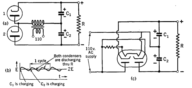
Figure 11 E (c) shows a doubler circuit which is often used without a transformer. The tube is called a double-diode rectifier. The full-wave doubler circuit has been generalized to give 4E, 6E, etc., and is then used to produce very high voltages for atom-smashing experiments.
|
||||
Home  Basic Circuits Basic Circuits  Rectifiers Rectifiers  Voltage-Doublers Voltage-Doublers |
||||
Last Update: 2009-11-01


