| Basic Radio is a free introductory textbook on electronics based on tubes. See the editorial for more information.... |

|

Home  Electronic Devices Electronic Devices  Cathode-Ray Tubes Cathode-Ray Tubes  Electron Guns Electron Guns |
||||||||


|
||||||||
|
Electron GunsAuthor: J.B. Hoag In many radio tubes there is a centralized filament surrounded by the various grids and plates. The electrons spread out from the filament radially in all directions. We might say that they are " broadcast." There is an entirely different class of tubes, namely, cathode-ray tubes, television tubes, positive-ray and atom-smashing machines, which require that the charged particles should not spread in all directions from their source but should be confined to a parallel beam, or, at most, should diverge but slightly along their entire route to the end plate.
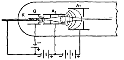
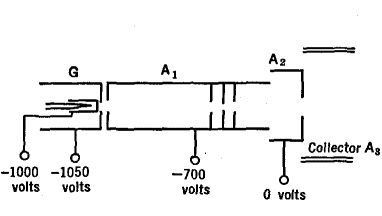
In front of the grid of Fig. 21 G, there is a cylinder A1 containing several metal diaphragms with holes in them. This is called the first anode. It is charged positively with respect to the cathode, to a potential of several hundred volts. Beyond the first anode there is a shorter but larger diameter anode A2, charged to a much higher potential, in some cases amounting to several thousand volts. The electric field set up between the two anodes serves, as in Fig. 21 F, to bring the electrons into a near-parallel beam. The electrostatic field between the two anodes can be shown to be the equivalent of a thick, unsymmetrical converging lens. Its focal length can be readily changed, within limits, by varying the voltage applied between the two anodes. In this respect, electron lenses are greatly superior to optical lenses. With a twist of the wrist to turn a rheostat, it is possible to change the focal length of the lens. Glass lenses cannot be so changed, but the crystalline lens of the human eye can be made of shorter focal length by the muscles which control it.
The gun structure of Fig. 21 H is used with television pickup tubes.
The gun of Fig. 21 I produces very intense electron beams (2 ma. at 10,000 volts concentrated into a spot only 0.3 mm. in diameter). It uses both electrostatic and magnetic focusing.
|
||||||||
Home  Electronic Devices Electronic Devices  Cathode-Ray Tubes Cathode-Ray Tubes  Electron Guns Electron Guns |
||||||||
Last Update: 2009-11-01


