| Basic Radio is a free introductory textbook on electronics based on tubes. See the editorial for more information.... |

|

Home  Transmission of Signals Transmission of Signals  Transmitters Transmitters  Checking Phone Transmitters Checking Phone Transmitters |
||||||||


|
||||||||
|
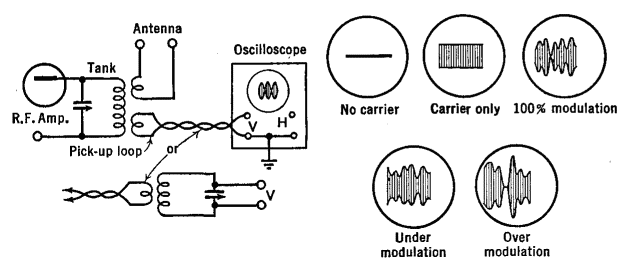
Checking Phone TransmittersAuthor: J.B. Hoag There are two methods of measuring modulation percentage by means of an oscilloscope. These are known as the wave-envelope and the trapezoid methods. For the first of these methods, a small amount of the transmitter's output is picked up with a few turns of wire and fed by a parallel or twisted wire or concentric line to the vertical deflecting plates of the oscilloscope, as in Fig. 31 I.
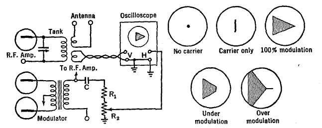
The second method of checking the modulation, the so-called trapezoidal method, differs from the one just described in that, instead of the linear horizontal sweep, the beam is deflected horizontally by the audio frequency from the speech amplifier. A suitable circuit for this purpose is shown in Fig. 31 J.
The sum of resistors R1 and R2 should be sufficiently great that only a small fraction of 1 milliampere flows through them. Roughly, their resistance should amount to one-quarter of a megohm for each 150 volts of modulator output. The blocking condenser C should be 0.1 μfd. or more. The patterns which appear on the screen are shown in the figure and should now be examined with care. Of the two methods, the latter is easier to interpret. Sometimes the sloping slides of the trapezoid are not perfectly straight. This may be due to imperfect neutralization of the amplifiers. Or it may be caused by incorrect C-bias, or weak excitation of the modulated amplifier, or both. If the amplifier is perfectly linear, which is the correct operating condition, the sides of the trapezoids will be perfectly straight. Sometimes the patterns on the oscilloscope differ radically from those shown in the figure. In this case one should seek for stray r.f. induced into the horizontal deflecting circuits of the oscilloscope, or for some trouble in the oscilloscope circuits themselves. If the power supplies applied to the transmitter have not been sufficiently filtered or if they have not been shielded from the r.f. circuits, an audio frequency hum will be superimposed upon the r.f. This modulation can be detected by listening with a receiver. If hum has been detected, proceed in the following manner: shut off the modulator; if hum persists, check the filtering of the power supplies of the different r.f. stages. Next, add the modulator, but not the speech amplifier. If the hum has still not been eliminated, the trouble lies in the speech amplifier or in the microphone. An oscilloscope, instead of a receiver, may be used in these tests for hum. Unless properly shielded from each other, r.f. voltages will be induced into the speech amplifier from the r.f. circuits, with the result that an audio frequency oscillation or " howl" will be set up. This will modulate the carrier frequency. The microphone, its cord, and the speech amplifier must be shielded and grounded to prevent this r.f. pickup.
|
||||||||
Home  Transmission of Signals Transmission of Signals  Transmitters Transmitters  Checking Phone Transmitters Checking Phone Transmitters |
||||||||
Last Update: 2009-11-01


