| Basic Radio is a free introductory textbook on electronics based on tubes. See the editorial for more information.... |

|

Home  Transmission of Signals Transmission of Signals  Direction Finders Direction Finders  Loop Antennas Loop Antennas |
||||||||||


|
||||||||||
|
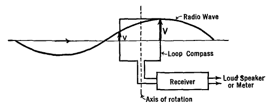
Loop AntennasAuthor: J.B. Hoag Consider a loop of wire placed in the path of a vertically polarized 1 radio wave. If its plane is set at right angles to the wave, equal voltages are induced in the two vertical arms, none in the horizontal wires. But the two voltages are in opposite directions, so that current cannot flow into an attached receiver, even if it is tuned to the transmitter; and there will be no output of sound, or any reading on an output electrical meter. On the other hand, if the plane of the loop is rotated about a central vertical axis until it is the same as that of the oncoming radio wave, the opposing voltages will not be equal in amount at a given instant and a current will flow through the tuned receiver circuits. This is illustrated in Fig. 34 A.
As the wave passes over the loop, the voltages induced in one of the vertical wires alternate at the same frequency as that of the radio wave, and in an amount proportional to its field intensity. But the voltage in one vertical wire reaches its peak value at a different moment than that in the other vertical arm of the loop. Hence we may say that the two voltages are out-of-phase with each other. When the plane of the loop is at right angles to the wave, the voltages are 180° out-of-phase (crest over trough), whereas with the plane of the loop the same as that of the oncoming wave, they are somewhat less than 180° out-of-phase.
The voltages induced in the loop are very small; a good deal of amplification is needed in the receiver. By using a large number of turns of wire instead of a single loop, this voltage can be proportionately increased. There is a limit to the number of turns which can be used, set by the necessity of tuning the loop to resonance with the highest frequency to be received. Another way of describing the directional receiving ability of a loop antenna is in terms of its response curve. As indicated in the idealized case of Fig. 34 B, maximum reception, and hence maximum output of the receiver, occur when the wave is in the plane of the loop, and zero reception occurs when it is at right angles to this plane.
If the wave comes in from some intermediate direction, say 6, the net voltage e from the two arms will be intermediate in value and of an amount represented by the length of the arrow marked e in this figure.
|
||||||||||
Home  Transmission of Signals Transmission of Signals  Direction Finders Direction Finders  Loop Antennas Loop Antennas |
||||||||||
Last Update: 2010-11-21


