| Basic Radio is a free introductory textbook on electronics based on tubes. See the editorial for more information.... |

|
Home  Transmission of Signals Direction Finders The Radio Compass or Goniometer Transmission of Signals Direction Finders The Radio Compass or Goniometer |
||||||||||


|
  |
|||||||||
|
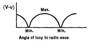
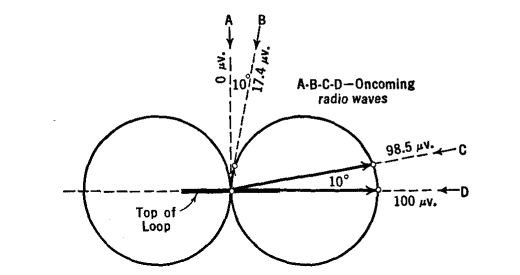
The Radio Compass or GoniometerAuthor: J.B. Hoag In order to determine the line of direction of a given transmitter, the loop is slowly rotated about a vertical axis. When the output of sound, or the reading of an output meter is a maximum, the plane of the loop is in line with the transmitter. When the output is a minimum, the plane of the loop is at right angles to the line of propagation. In practice it is found possible to judge the minimum more accurately than the maximum. The reason for this will be clear from a study of Figs. 34 C and D.
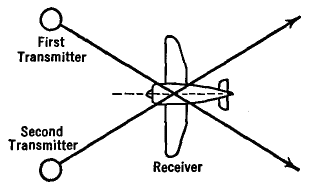
This simple compass, however, shows only the path of the radio wave. It does not tell whether the transmitter lies ahead of, or behind, the receiver. Cross bearings may be taken on two transmitters. The receiver is tuned to one station, its loop is rotated to a minimum, and the angle noted. This procedure is repeated for the second transmitter. The two directions are then laid out on a map. Their intersection is at the location of the receiver. See Fig. 34 E.
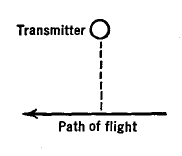
A different method, often used by commercial airlines in the United States, when a plane is flying along a known path, say along a radio beam, is to fix the loop with its plane the same as the heading of the airplane and to tune the receiver to a station located somewhere off the known path. See Fig. 34 F.
Then, just as the airplane passes directly opposite the transmitter, the signal drops to a minimum. From his maps, the pilot may then say that he is on such-and-such a path and is so-and-so many miles due south, say, from the particular town where the transmitter is placed.
|
||||||||||
| Home Transmission of Signals Direction Finders The Radio Compass or Goniometer |
|
|||||||||
Last Update: 2009-11-01