| Basic Radio is a free introductory textbook on electronics based on tubes. See the editorial for more information.... |

|
Home  Transmission of Signals Short-Lines Short-Wire Antennas Transmission of Signals Short-Lines Short-Wire Antennas |
|||||||||||||||||||||||
| See also: Simple Antennas, Long-Wire Antennas, Short-Lines | |||||||||||||||||||||||


|
  |
||||||||||||||||||||||
|
Short-Wire AntennasAuthor: J.B. Hoag The half-wave Hertz type of antenna is used extensively today. Figure 36 J shows the current distribution on end-fed and center-fed half-wave antennas, together with the resonant quarter-wave feeders and the coupling condensers and inductances.
The actual length l of the wires in a half-wave antenna is somewhat less than one-half the wave-length of the radio wave in free space.
The feeders may be one-quarter of a wave-length long, or any whole number multiple of a quarter-wave. Series tuning is used when the bottom of the feeder has high current and low voltage (low impedance) , as on the left side of Fig. 36 J. Parallel tuning is used when the current is a minimum (voltage is a maximum) at the bottom of the feeder, as in the right-hand side of this figure. The end-fed antenna is also called a " Zepp " or voltage-fed-antenna. The center-fed system is sometimes referred to as a current-fed system. Non-resonant lines may also be used to feed from the transmitter to the half-wave antenna. From top to bottom, in Fig. 36 K, they are called: single feed, twisted pair, concentric, and delta matched feeders.
The adjustment of the antenna's impedance (to be taken up shortly) to that of the line can be accomplished by means of a linear-transformer, as in Fig. 36 L.
The point at which the untuned line is attached to the quarter-wave feeder is adjusted until all energy fed from the line is absorbed into the antenna. The output impedance of the non-resonant line is then equal to its characteristic impedance (see Long-Lines) . The lower system in Fig. 36 L is called a " J " antenna. An antenna must radiate as much energy as possible in the form of an electromagnetic wave. In the case of a resistor, we have spoken of its ability to dissipate energy in the form of heat by using the term " resistance " (= watt-lost divided by current-squared) . It is common practice to use a fictitious " resistance," called radiation-resistance, to measure the amount of radio power sent out from an antenna. All other factors being the same, the greater the radiation-resistance, the better the antenna. The value for a half-wave antenna in free space, measured at the center of the wire where the current is greatest, is 73.2 ohms. The value changes as the antenna is moved closer to the ground, because energy reflected from the ground sets up voltages in the antenna. See Fig. 36 M.
The value, measured at the end of a half-wave antenna in free-space is approximately 2,400 ohms. Other losses from an antenna, such as those due to ohmic resistance, corona discharge, and insulator losses are small, say 5 per cent of the power put into the antenna. The half-wave antenna may be mounted vertically or horizontally. With the wire straight up and down, it radiates (and receives) equally well from all directions. When horizontal, however, it sends out more energy (and also receives better) from the direction at right angles to the wire. The field patterns " laid down " by isolated antennas, one-half, one, and two wave-lengths long, are shown in Fig. 36 N.
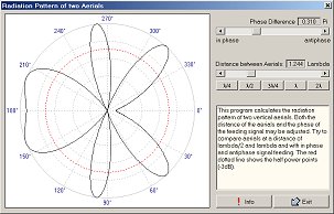
A line from the center of the antenna to the curved " lobes " is proportional to the strength of the signal radiated in that direction. It will be noticed that the half-wave antenna gives bi-directional, " broadside " radiation. When a longer antenna is used, the radiation is broken up into a whole lot of weaker radiations, scattered at various directions. In other words, if you want to direct the radiation (more or less sharply), use a quarter-wave antenna, but if you wish to broadcast the energy, use a longer one. By combining half-wave antennas, at correct spacings and with their currents properly phased, strong radiation can be obtained either broadside to the array or in its line (" end-fire " systems). Figure 36 0 shows the field patterns when eight vertical dipoles are used.
In the end-fire system at the left, the currents in adjacent dipoles are 180° out-of-phase with each other and the pattern is fairly broad. At the right of Fig. 36 0, the currents in all dipoles flow in the same direction at the same time (in-phase) and a sharp broadside radiation takes place on both sides of the antenna. Figure 36 P shows the top view (the dots) of a row of vertical dipoles spaced one-quarter wave from each other and with currents in quadrature (90°) (max. in one, when min. current in next wire).
In this case, a broad beam is obtained, but it is in only one direction, say east, and not along a line, say east-west.
In Fig. 36 Q, the sharpness of the broadside antenna of Fig. 36 0 and the uni-directional feature of Fig. 36 P have been combined by using tuned wire reflectors one-quarter of a wave behind a broadside antenna. The more dipole and reflector wires used, the sharper the beam and the smaller the side lobes.
Figure 36 R shows a half-wave antenna with two parasitic elements. This system is directive towards the right, in increasing amount as more and more directors are added (with the same spacing).
|
|||||||||||||||||||||||
| Home Transmission of Signals Short-Lines Short-Wire Antennas |
|
||||||||||||||||||||||

Last Update: 2009-11-01