An U.H.F. Transmitter
Author: J.B. Hoag
 |
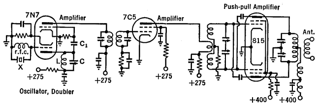
| Fig. 37 E. Circuit diagram of an u h.f. transmitter |
The circuit diagram of the u.h.f. transmitter of Fig. 37 E looks the same as though the unit had been built for operation at much lower frequencies. There is a crystal oscillator (lower half of the 7N7 tube) whose plate tank LC is tuned to twice the fundamental frequency of the crystal. The r.f. voltages across LC are fed through C1 to the grid of the first amplifier (upper half of the 7N7 tube). The h.f. is then coupled through a tuned transformer to the 7C5 beam-power second-doubler amplifier and from there to the neutralized push-pull amplifier using an 815 double-beam-power tube. At the ultra-high frequencies, the tuning condensers are small both electrically, (10 to 100 pF) and physically, but the coils, while small electrically, are comparatively large in physical dimensions, the more so the higher the frequency. Around 100 MHz, for example, the 815 tank coil may consist of a foot and a half of quarter-inch copper tubing bent into a circle six inches in diameter, with a quarter of an inch spacing between turns. This gives the completed transmitter an entirely different appearance from one operated at lower frequencies. At the higher frequencies, the tank circuit of the 815 tube may well be replaced with a parallel-line linear-circuit in order to attain lower losses and higher output.
|


 Transmission of Signals
  U.H.F. Transmitters and Receivers
  An U.H.F. Transmitter


 Transmission of Signals
  U.H.F. Transmitters and Receivers
  An U.H.F. Transmitter

