| Electronic Transformers and Circuits is a free introductory textbook on transformers and related circuits. See the editorial for more information.... |

|

Home  Introduction Introduction  Equivalent Circuit and Vector Diagram Equivalent Circuit and Vector Diagram |
|||||||||||||||


|
|||||||||||||||
Equivalent Circuit and Vector Diagram
For purposes of analysis the transformer may be represented by a 1:1 turns ratio equivalent circuit. This circuit is based on the following assumptions:
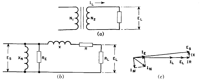
With many sine-wave electronic transformers, the transformer load is resistive. A tube filament heating load, for example, has 100 per cent power factor. Under this condition the relations between voltages and currents become appreciably simplified in comparison with the same relations for reactive loads. In what follows, the secondary winding will be chosen as the reference winding. At low frequencies such a transformer may be represented by Fig. 3 (a).
The transformer equivalent circuit is approximated by Fig. 3(b), and its vector diagram for 100 per cent p-f load by Fig. 3(c). Secondary load voltage EL and load current IL are in phase. Secondary induced voltage Es is greater than EL because it must compensate for the winding resistances and leakage reactances. The winding resistance and leakage reactance voltage drops are shown in Fig. 3(c) as IR and IX, which are respectively in phase and in quadrature with IL and EL. These voltage drops are the sum of secondary and primary winding voltage drops, but the primary values are multiplied by a factor to be derived later. If voltage drops and losses are temporarily forgotten, the same power is delivered to the load as is taken from the line. Let subscripts 1 and 2 denote the respective primary and secondary quantities.
or
so that the voltages are inversely proportional to the currents. Also, from equation 2, they are directly proportional to their respective turns.
Now the transformer may be replaced by an impedance Z1 drawing the same current from the line, so that
where Z2 is the secondary load impedance, in this case RL , If these expressions for current are substituted in equation 6,
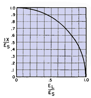
Equation 7 is strictly true only for negligible voltage drops and losses. It is approximately true for voltage drops up to about 10 per cent of the winding voltage or for losses less than 20 per cent of the power delivered, but it is not true when the voltage drops approach in value the winding voltage or when the losses constitute most of the primary load. Not only does the load impedance bear the relation of equation 7 to the equivalent primary load impedance; the winding reactance and resistance may also be referred from one winding to the other by the same ratio. This can be seen if the secondary winding resistance and reactance are considered part of the load, across which the secondary induced voltage Es appears. Thus the factor by which the primary reactance and resistance are multiplied, to refer them to the secondary for addition to the secondary drops, is (N2/N1)2. If the primary had been the reference winding, the secondary reactance and resistance would have been multiplied by (N2/N1)2. In Fig. 3(c) the IR voltage drop subtracts directly from the terminal voltage across the resistive load, but the IX drop makes virtually no difference. How much the IX drop may be before it becomes appreciable is shown in Fig. 4.
If the IX drop is 30 per cent of the induced voltage, 4 per cent reduction in load voltage results; 15 per cent IX drop causes but 1 per cent reduction.
|
|||||||||||||||
Home  Introduction Introduction  Equivalent Circuit and Vector Diagram Equivalent Circuit and Vector Diagram |
|||||||||||||||
Last Update: 2011-01-24


