| Electronic Transformers and Circuits is a free introductory textbook on transformers and related circuits. See the editorial for more information.... |

|

Home  Introduction Introduction  Magnetizing Current Magnetizing Current |
||||||||


|
||||||||
Magnetizing Current
Core-loss current is often divided into two components: eddy current and hysteresis. Eddy-current loss is caused by current circulating in the core laminations. Hysteresis loss is the power required to magnetize the core first in one direction and then in the other on alternating half-cycles. Hysteresis loss and magnetization are intimately connected, as can be seen from Fig. 5.
Here induced voltage e is plotted against time, and core flux Φ lags e by 90°, in accordance with equation 3. This flux is also plotted against magnetizing current in the loop at the right. This loop has the same shape as the B-H loop for the grade of iron used in the core, but the scales are changed so that
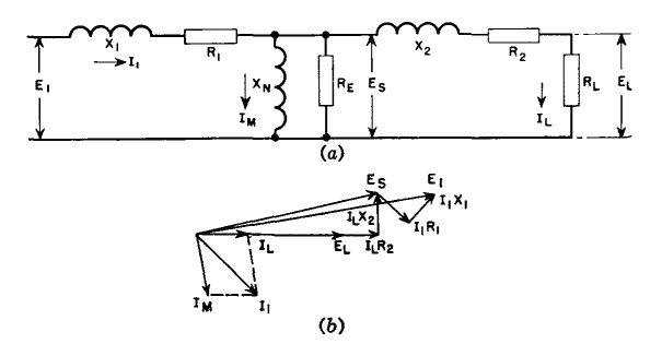
where B = core flux density in gauss Current is projected from the Φ-i loop to obtain the alternating current i at the bottom of Fig. 5. This current contains both the magnetizing and the hysteresis loss components of current. In core-material research it is important to separate these components, for it is mainly through reduction of the B-H loop area (and hence hysteresis loss) that core materials have been improved. Techniques have been developed to separate the exciting current components, but it is evident that these components cannot be separated by current measurement only. It is nevertheless convenient for analysis of measurements to add the loss components and call their sum IE, and to regard the magnetizing component IM as a separate lagging current, as in Fig. 3. As long as the core reactance is large, the vector sum IN of IM and IE is small, and the non-sinusoidal shape of IN does not seriously affect the accuracy of Fig. 3. Core flux reactance may be found by measuring the magnetizing current, i.e., the current component which lags the applied voltage 90° with the secondary circuit open. Because of the method of measurement, this is often called the open-circuit reactance, and this reactance divided by the angular frequency is called the open-circuit inductance. The secondary and primary winding leakage reactances are found by short-circuiting the secondary winding and measuring the primary voltage with rated current flowing. The component of primary voltage which leads the current by 90° is divided by the current; this is the sum of the leakage reactances, the secondary reactance being multiplied by the (turns ratio)2, and is called the short-circuit reactance. Practical cases sometimes arise where the magnetizing component becomes of the same order of magnitude as IL. Because current IM flows only in the primary, a different equivalent circuit and vector diagram are necessary, as shown in Fig. 6.
Note that the leakage reactance voltage drop has a marked effect upon the load voltage, and this effect is larger as Im increases relative to IL. Therefore, the statement that IX voltage drop causes negligible difference between secondary induced and terminal voltages in transformers with resistive loads is true only for small values of exciting current. Moreover, the total primary current I1 has a largely distorted shape, so that treating the IR and IX voltage drops as vectors is a rough approximation. For accurate calculation of load voltage with large core exciting current, a point-by-point analysis would be necessary.
|
||||||||
Home  Introduction Introduction  Magnetizing Current Magnetizing Current |
||||||||
Last Update: 2011-01-24


