| Electronic Transformers and Circuits is a free introductory textbook on transformers and related circuits. See the editorial for more information.... |

|

Home  Rectifier Transformers and Reactors Rectifier Transformers and Reactors  Filament Transformer Design Filament Transformer Design |
||||||||||||||||||||||||
| See also: Filament Transformers | ||||||||||||||||||||||||


|
||||||||||||||||||||||||
Filament Transformer Design
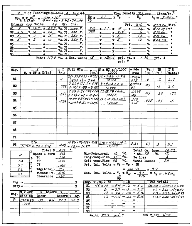
It is important that design work be done systematically to save the designer's time and to afford a ready means of finding calculations at a later date. To attain these ends a calculation form, such as that in Fig. 55, is used.
The form is usually made to cover several kinds of transformers, and only the spaces applicable to a filament transformer are used. Suppose that a transformer is required to supply filament power for four single-phase full-wave rectifiers having output voltages of 2,000, 500, 250, and 250 volts, respectively, with choke-input filters, as follows:
Primary voltage 100
Frequency 60 cycles Four secondaries for the following tube filaments:
Ambient temperature: 40°C
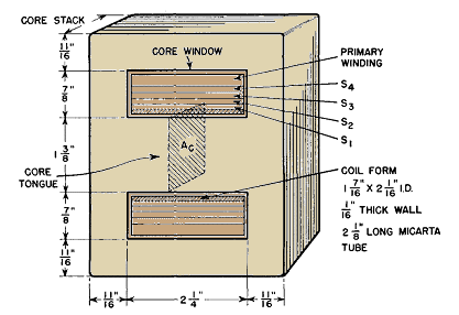
First comes the choice of a core. Data such as those in Fig. 43 are helpful in this, and so is design experience in the modification of such data by the specified requirements. The core used here is a 2-in. stack of laminations A, Fig. 44, which is described more fully in Fig. 56, and has enough heat dissipation surface for this rating.
For silicon steel, an induction of 70,000 lines per square inch is practical. The primary turns can be figured from equation 4 by making the substitution Φ = BAc and transposing to
where Ac is the core cross-sectional area, or product of the core tongue width and stack dimension, and B is the core induction. In this transformer, with 90 per cent stacking factor, Ac = 2 · 0.9 · 1.375 = 2.48 sq in., and the primary turns are found to be 216.
Next an estimate of the regulation is made (10 per cent) and added to unity to obtain the multiplier 1.1 in the estimate of secondary turns near the top of the calculation form. From the currents listed, the wire size for each winding is chosen. Round enameled wire is used for each winding except S1, and for it No. 12 square wire is used to save space. The largest wire is placed next to the coil form to prevent damage in winding to the smaller wires. The next task is to find out whether the wire chosen will fit in the core window space. Winding height D is entered for each winding. For each secondary this is the wire diameter, because the wire is wound in a single layer. D for S1 is slightly larger than the wire dimension to allow for the bulge that occurs when square wire is wound. The twelve turns of S1 occupy about 1 1/4 in. of horizontal winding space. The core window is 2 1/4 in. wide. From this is subtracted 1/8 in. for clearance, leaving 2 1/8 in. total coil width. Margins on each side of S1 are therefore 1/2 (2 1/8 - 1 1/4) = 7/16 in. According to Fig. 40 (p. 48) this provides over 8 kv breakdown strength, which is well above the 5-kv test voltage for S1. Other secondary windings have lower test voltages and wider margins, and hence have more than adequate creepage distances. The 1/16-in.-thick Micarta rectangular tube used for the coil form has a corona voltage of 2,700 rms, which affords about 23 per cent safety factor over the normal operating voltage at the tube filaments. Over S1 are wound six wraps of 0.010-in.-thick treated cloth, which has 2,600-volt corona limit. Winding S2 supplies a filament at 500 volts of the same polarity as S1. Hence only 1,500 volts direct current or 1,660 volts alternating current occur across this insulation. At the right of the small sketch in Fig. 55 are listed the number of wraps of 0.010-in.-thick treated cloth over each section of winding. These are added together to give the columnar figure of 0.150 for TC. The primary winding is wound without layer insulation and with an area space factor of 70 per cent. Cotton is wound in with the wire to form walls 3/16 in. thick on either side of the primary; this accounts for the low space factor and for the 1 3/4-in. winding traverse. The coil is finished with two layers of treated cloth, a layer of 0.010-in. fishpaper for mechanical protection, and a 0.025-in. serving of untreated cotton yarn or tape to hold it together. The total winding adds up to 0.751 in., leaving 0.124 in. clearance, about the right allowance for winding slack for four secondaries. Mean turns are figured from equations 26 and 27, with 5 per cent incremental increase in S2, S3, and S4 for leads. With the mean turn values the winding resistances, weights of copper, and IR and I2R for each winding can be found. To S1, S2, and S3 winding resistance is added lead resistance, and the lower figure is the sum of the two in each case. Total copper loss is multiplied by 1.3 to correct for 75°C operating temperature. The core weight is 6.8 lb, and the grade of steel used has 1.17 watts per pound at 70,000 lines per square inch. This gives a core loss of 8 watts, and a total of copper and core loss of 20 watts. After these losses are divided by the appropriate ordinates from Figs. 44 and 45 the coil temperature rise is figured at 48 centigrade degrees, which is safe for class A insulation. We know by now that the design is safe, but secondary voltages still must be checked. The method of equation 13 is used. Output voltages on first trial range from 0 to 4 per cent high. S2 voltage is correct but out of line with the rest. Changing S2 leads to a larger size makes the per cent voltage drops more nearly alike, and increasing the primary turns to 223 brings all output voltages to correct value within 1.2 per cent. Filament voltage should be kept within 2 per cent for these tubes, to allow for meter error. Primary voltage per layer is checked at the lower left; this is equivalent to 22.7 volts per mil of wire enamel, which is safe practice. If the design were deficient in any respect, even down to the last things figured, some change would have to be made which would require recalculation of all or part of the transformer; hence the importance of good estimating all the way along. The filament transformer outlined above had a center tap (C.T.) in each filament winding. Such taps are used with directly heated cathodes, especially when plate current is large, to prevent uneven distribution of filament emission. In windings for supplying filaments of small tubes, center taps are sometimes omitted. Ripple in the rectified output then increases, and transformer core flux density becomes asymmetrical. Whether these effects are permissible depends on operating conditions. Usually plate current is much smaller than filament current, so that center-tap leads may be smaller in copper section than start and finish leads. A certain amount of space is required for these leads; rectifier wiring is also more time-consuming when there are center taps. Nevertheless, the extra work and size may be justified by improved performance. An even number of turns, such as were used in the transformer windings described in this section, results in center-tap placement on the same coil end as the start and finish leads; if there were an odd number of turns, the tap lead would be at the opposite end. In a single-core, single-coil design, an odd number of turns cannot be center-tapped exactly. Usually the unbalance caused by the tap being a half-turn off center is not serious, but it should not be disregarded without calculation.
|
||||||||||||||||||||||||
Home  Rectifier Transformers and Reactors Rectifier Transformers and Reactors  Filament Transformer Design Filament Transformer Design |
||||||||||||||||||||||||
Last Update: 2011-01-24


