| Electronic Transformers and Circuits is a free introductory textbook on transformers and related circuits. See the editorial for more information.... |

|

Home  Rectifier Transformers and Reactors Rectifier Transformers and Reactors  Anode Transformer Design Anode Transformer Design |
|||||||
| See also: Anode Transformers, Combined Anode and Filament Transformers | |||||||


|
|||||||
Anode Transformer Design
To fulfill these requirements, a reactor-input filter must be used. If 1 per cent is allowed for reactor IR drop, a maximum of 4 per cent regulation is left in the anode transformer. The approximate secondary output voltage is 1,200 · 2.22 = 2,660, say 2,700 volts. The center tap may be grounded. Suppose that a transformer like the one in Fig. 57 is used. The calculations are given in Fig. 58. The various steps are performed in the same order as in filament transformers. The grain-oriented type C core is worked at 38 per cent higher induction, with but 60 per cent of the core loss of Fig. 55; its strip width is 2% in., build-up % in., and window 1 in. by 3 in. for each core loop. Note the difference in primary and secondary volt-amperes and winding heights. Since the primary and secondary are symmetrical about the primary horizontal center line, they have the same mean turn length. Losses and temperature rise are low. Regulation governs size. Secondary layer voltage is high enough to require unusually thick layer paper. This coil is wound on a multiple-coil machine. Winding height is figured on the basis of layer paper adequate for the voltage instead of from Table VI (p. 39), but turns per layer are taken from this table. Since adjacent layers are wound with opposite directions of traverse, the highest voltage across the layer insulation is twice the volts per layer. Layer insulation is used at 46 volts per mil in the secondary; this counts the 1.7 mils of double enamel, which must withstand impregnation without damage. Anode leads and margins withstand 5 kv rms test voltage. Since the secondary center tap is grounded, two thicknesses of 0.010-in. insulation between windings are sufficient. Clearance of 0.253 in. allows room for in-and-out coil taping. Secondary leakage inductance, from equation 33, is
At 60 cycles this is 6.28 · 60 · 0.166 = 63 ohms, which would be 240 ohms if the secondary were a single section, and which would increase regulation as set forth in Rectifier Performance. The regulation calculated in Fig. 58 is that due to primary IR calculated in the normal manner, plus Idc times one-half the secondary winding resistance.
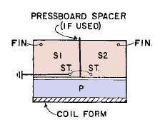
When high voltage is induced in a winding, the layer insulation and coil size may often be reduced by using the scheme shown in Fig. 59.
This is applicable to a plate transformer of the single-phase full-wave type with center tap grounded. It then becomes practical to make the secondary in two separately wound vertical halves or part coils. One of the part coils is assembled with the turns in the same direction as those of the primary, and the other part coil is reversed so that the turns are in the opposite direction. The two start leads are connected together and to ground as in Fig. 59. It is necessary then to provide only sufficient insulation between windings to withstand the primary test voltage. Channels may be used to insulate the secondaries from the core. With higher voltages, it may be necessary to provide pressboard spacers between the secondary part coils, or to tape the secondary coils separately, but margins must be provided sufficient to prevent creepagc across the edges of the spacers.
|
|||||||
Home  Rectifier Transformers and Reactors Rectifier Transformers and Reactors  Anode Transformer Design Anode Transformer Design |
|||||||
Last Update: 2011-01-24


