Design Chart
In preceding sections, it has been stated that special conditions require tailored designs. Windings for simple low-voltage 60-cycle transformers may be chosen from the chart of Fig. 63. This chart is based upon the following conditions:
- Two untapped concentric windings; primary wound first.
- Operating voltage in both windings less than 1,000 volts.
- Power supply frequency 60 cycles.
- Maximum temperature rise 40°C in 65°C ambient.
- Resistive loads.
- Equal I2R losses in primary and secondary,
- Solventless resin impregnated coils.
- Open-type assemblies like those of Fig. 15.
- Grain-oriented silicon-steel cores.
It was found that 40°C rise in the four smallest sizes resulted in excessive voltage regulation. For example, a small filament transformer would deliver correct filament voltage at room ambient temperature of 25 °C, but at 105°C this voltage dropped to less than the published tube limit. Hence the winding regulation in the two smallest transformers was limited to 15 per cent, and in the next two larger sizes to 10 per cent. In still larger sizes, the 40°C temperature limit held the regulation to less than 10 per cent.
In using the chart, ratings rarely fall exactly on the v-a values assigned to each core. Hence a core is generally chosen with somewhat greater than required rating. Lower regulation and temperature rise than maximum then result. Wire size in quadrant I also increases in discrete sizes, and if the chart indication falls between two sizes the smaller size should be used.
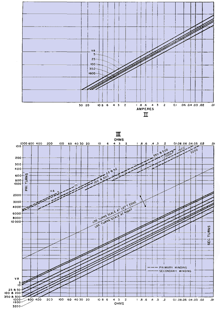
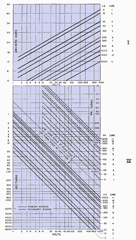
Instructions for Using Fig. 63.
- Choose a core from Table VIII which has a v-a rating equal to or greater than that required.
- From rated primary and secondary voltages, find number of turns for both windings in quadrant IV.
- From rated primary and secondary currents, find wire size for both windings in quadrant I.
- Project turns across to quadrant III to obtain winding resistances.
Table VIII. Transformer Size, Rating, and Regulation
 |
| Figs. 63. Low-voltage 60-cycle transformer design chart. |
 |
| Fig. 63. (Continued) |
Departures from the assumed conditions preclude direct application of Fig. 63, but the chart is still useful as a starting point in design. For some common modifications, the following notes apply:
- For each additional secondary winding reduce core maximum rated volt-amperes by 10 per cent. Choose wire size from quadrant II.
- For 50-cycle transformers, reduce core maximum rated v-a 10 per cent.
- When permissible temperature rise is higher than 40°C, core maximum volt-amperes equal (v-a in table) ∙
Example. A transformer is required for 115/390 volts, 60 cycles, to deliver 77 volt-amperes. This rating falls between the maxima for cores 4 and 5. Using core 5 at 115 volts, we read, from Fig. 63, for the primary, 440 turns of No. 22 wire and 3 ohms d-c resistance; for the secondary, 1,700 turns of No. 27 wire and 40 ohms d-c resistance.
|
 Rectifier Transformers and Reactors


