| Electronic Transformers and Circuits is a free introductory textbook on transformers and related circuits. See the editorial for more information.... |

|

Home  Rectifier Performance Rectifier Performance  Capacitor Effect Capacitor Effect |
|||||||||||||||


|
|||||||||||||||
Capacitor Effect
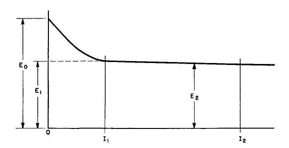
Suppose that the rectifier circuit shown in Fig. 80(a) delivers single-phase full-wave rectifier output as shown in Fig. 80(b) to an inductor-input filter and thence to a variable load. In such a circuit, the filter inductor keeps the capacitor from charging to a value greater than the average Edc of the rectified voltage wave at heavy loads. At light loads the d-c output voltage rises above the average of the rectified wave, as shown by the typical regulation curve of Fig. 89.
Starting at zero load, the d-c output voltage E0 is 1.57 times the average of the rectified wave. As the load increases, the output voltage falls rapidly to E1 as the current I1 is reached. For any load greater than I1 the regulation is composed only of the two components IR and IX. It is good practice to use a bleeder load I1 so that the rectifier operates between I1 and I2. Filter elements XL and Xc determine the load I1 below which voltage rises rapidly. The filter, if it is effective, attenuates the a-c ripple voltage so that across the load there exists a d-c voltage with a small ripple voltage superposed. A choke-input filter attenuates the harmonic voltages much more than the fundamental, and, since the harmonics are smaller to begin with, the main function of the filter is to take out the fundamental ripple voltage. This has a peak value, according to Fig. 83, of 66.7 percent of the average rectified d-c voltage for a single-phase full-wave rectifier. Since this ripple is purely a-c it encounters a-c impedances in its circuit. If we designate the choke impedance as XL, and the capacitor impedance as XC, both at the fundamental ripple frequency, the impedance to the fundamental component is XL - Xc, the load resistance being negligibly high compared to Xc in an effective filter. The d-c voltage, on the other hand, produces a current limited mainly by the load resistance, provided that the choke IR drop is small.
A-c and d-c components are shown in Fig. 90, with the ripple current Iac superposed on the load direct current Idc. If the direct current is made smaller by increased load resistance, the a-c component is not affected because load resistance has practically no influence in determining its value. Hence a point will be reached, as the d-c load current is diminished, where the peak value of ripple current just equals the load direct current. Such a condition is given by d-c load I1 which is equal to Iac. If the d-c load is reduced further, say to the value Ix, no current flows from the rectifier in the interval A-B of each ripple cycle. The ripple current is not a sine wave, but is cut off on the lower halves, as in the heavy line of Fig. 91.
Now the average value of this current is not Ix but a somewhat higher current Iy. That is, the load direct current is higher than the average value of the rectified sine wave voltage divided by the load resistance. This increased current is caused by the tendency of the capacitor to charge up to the peak of the voltage wave between such intervals as A-B; hence the term capacitor effect which is applied to the voltage increase. The limiting value of voltage is the peak value of the rectified voltage, which is 1.57 times the sine-wave average, at zero load current. To prevent capacitor effect the choke must be large enough so that Iac is equal to or less than the bleeder current I1. This consideration leads directly to the value of choke inductance. The bleeder current I1 is E1/R1, where R1 is the value of bleeder resistance. The ripple current is the fundamental ripple voltage divided by the ripple circuit impedance, or
Equating I1 and Iac we have, for a single-phase full-wave rectifier,
Here we see that the value of capacitance also has an effect, but it is minor relative to that of the choke. In a well-designed filter, the choke reactance XL is high compared to Xc. Therefore, the predominant element in fixing the value of R1 (and of I1) is the filter reactor. Polyphase rectifiers have similar effects, but the rise in voltage is not so great because of the smaller difference between peak and average d-c output. The bleeder resistance for eliminating capacitor effect can be found in general from
where P1 is the fundamental ripple peak amplitude from Fig. 83, and XL and Xc are the filter reactances at fundamental ripple frequency. Between load I1 and zero load, the rate of voltage rise depends upon the filter. Figure 92 shows the voltage rise as a function of the ratio (XL - XC)/RL for a single-phase full-wave rectifier. A curve of ripple in terms of ripple at full load is given. Figure 92 is a plot of experimental data taken on a rectifier with IR + IX regulation of 5 percent. Reactances XL and Xc are computed for the fundamental ripple frequency. Capacitor-input filters have the voltage regulation curves shown in Figs. 50, 51, and 53) (pp. 64, 65, and 68) for their respective circuits. At light loads these filters may give reasonably good regulation, but it is possible to get very poor regulation at heavier loads, as can be seen from the curves. Rectifier series resistance plays an important part in the voltage regulation of this type of filter. The effect of anode transformer leakage inductance can be found from Fig. 92.
|
|||||||||||||||
Home  Rectifier Performance Rectifier Performance  Capacitor Effect Capacitor Effect |
|||||||||||||||
Last Update: 2011-01-24


