| Electronic Transformers and Circuits is a free introductory textbook on transformers and related circuits. See the editorial for more information.... |

|

Home  Amplifier Transformers Amplifier Transformers  High-Frequency Response High-Frequency Response |
||||||||||||||||||||


|
||||||||||||||||||||
High-Frequency Response
At any frequency, the equivalent voltage ratio in the circuit of Fig. 107(e) can be found by the ratio of impedances, as for the low-frequency response. The scalar value is
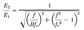
In equation 63 the term XL/XC may be written 4π2f2LC = f2/fr2, where 1/(2π√(LC)) = fr , the resonance frequency of the leakage inductance and winding capacitance, considered as lumped and without resistance. Also XL/R2 = XCf2/R2fr2. Assign to the ratio Xc/R1 a value B at frequency fr. Then at any frequency f, Xc/R1 = Bfr/f. In the three cases considered at the low frequencies, R2 = R1,
R2 = 2R1,
R2 = ∞,
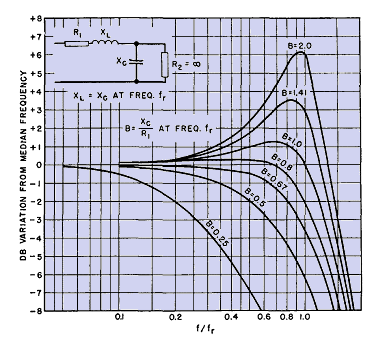
Equations 63a, b, and c are plotted in Figs. 109, 110, and 111. If Xc/R1 has certain values at frequency fr, the frequency characteristic is relatively flat up to frequencies approaching fr. In particular, performance is good at B = 1.0 in all three figures.
When leakage inductance and winding capacitance are regarded as "lumped" quantities, current distribution in the windings is assumed to be uniform throughout the range of frequencies considered. As shown in R-F Chokes, this assumption is valid up to the resonance frequency fr. At frequencies higher than fr, there may be appreciable error in Figs. 109, 110, and 111. But good frequency characteristics lie mainly below the frequency fr, where the curves are correct within the assumed limits.
To use these curves in design work, choose the most desirable characteristic curve and, from a knowledge of the source impedance, find the proper value of capacitive reactance Xc at frequency fr. The value of fr should be such that the highest frequency to be covered lies on the flat part of the curve. Xo and fr determine the values of winding capacitance and leakage inductance that must not be exceeded in order to give the required performance. In Fig. 107(e) the capacitance is shown across the load. This is correct if the main body of capacitance is greater on the secondary than on the primary side. Normally this is true if the secondary winding has the greater number of turns. Figures 109, 110, and 111 are thus plotted specifically for step-up transformers.
Modifications are necessary for step-down transformers, the equivalent circuit for which is shown in Fig. 113. Analysis shows the scalar voltage ratio to be
Notice the similarity to equation 63. In fact, if R1 = R2, equation 64 reduces to equation 63; for this case the response is the same for step-down and step-up transformers, and is given by Fig. 109. For R2 = 2R1 ; equation 64 becomes, after substitution in terms of frequency,
which is plotted in Fig. 113. Non-uniform response comes at somewhat lower frequency than in Fig. 110. The case of R2 = ∞ for step-down transformers is not important. By inspection it can be seen to be the response of R1 and Xc in series, because XL carries no current. This case rarely occurs in practice.
|
||||||||||||||||||||
Home  Amplifier Transformers Amplifier Transformers  High-Frequency Response High-Frequency Response |
||||||||||||||||||||
Last Update: 2011-01-24


