| Electronic Transformers and Circuits is a free introductory textbook on transformers and related circuits. See the editorial for more information.... |

|

Home  Amplifier Circuits Amplifier Circuits  Design Examples Design Examples  Transformer for Pi-Filter Modulator Transformer for Pi-Filter Modulator |
|||||


|
|||||
Design Example - Transformer for Pi-Filter Modulator
Audio output 400 watts. Power amplifier EB/IB = 10,000 ohms. Voltage ratio primary/secondary (1,180 + 1,180)/2,000. f1 = 60 cycles. Core: 4-in. stack of silicon-steel lamination B, Fig. 44. Turns primary/secondary (800 + 800)/1,380 No. 26 wire. Ac = 7.2 sq in. net; 8.0 sq in. gross. lc = 12.75 in. lg = 0.012 in. Possible tube current unbalance = 0.032 amp.
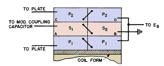
XL at f1 = 6.28 · 60 · 36.5 = 13,800 ohms. Zs = 115 per cent R at 100 cycles from Fig. 146. Winding arrangement as in Fig. 158, to reduce layer voltage and capacitance. Winding resistances: Total primary 90 ohms. Secondary 80 ohms. Secondary leakage inductance = 53 millihenrys. Capacitances (referred to secondary): P1 - S1(at A) = 292 μμf P1 - S2(at B) = 0 P2 - S1(at C) = 112 P2 - S2(at D) = 58 Secondary layer to layer = 140 Primary layer to layer = 170 Stray and tube = 50 Power amplifier r-f bypass = 500 ---------------------------------- Total = 1,322 μμf
At high audio frequencies fr = 19,000, D = 0.6, and Z/R2 from Fig. 119 (p. 159) is 87 per cent at 5,000 cycles.
|
|||||
Home  Amplifier Circuits Amplifier Circuits  Design Examples Design Examples  Transformer for Pi-Filter Modulator Transformer for Pi-Filter Modulator |
|||||
Last Update: 2011-01-24


