| Electronic Transformers and Circuits is a free introductory textbook on transformers and related circuits. See the editorial for more information.... |

|

Home  Amplifier Circuits Amplifier Circuits  Amplifier Tests Amplifier Tests |
||||


|
||||
Amplifier Tests
Tests for hum, distortion, linearity, and frequency response can be made with meters in the output circuit when voltage of a known frequency and wave form is applied to the input. Hum and distortion are conveniently measured by instruments specially made for the purpose. Linearity is measured by varying the input voltage and measuring corresponding output voltage. Frequency response is measured at a fixed input or output voltage, but frequency is varied. Normal production testing of amplifiers requires no more than such overall tests. But, in the development of the amplifier, excessive hum, distortion, or other defects may be indicated, and tests must be applied stage by stage to locate the trouble. Voltage is usually measured by a tube voltmeter, one terminal of which is grounded. In a push-pull amplifier, it is therefore necessary to block the direct voltage and measure the alternating voltage on each side. A cathode-ray oscilloscope is helpful in checking phase shift and wave form at various points.
Balance (an important property of push-pull amplifiers) and shielding tests are described in Standard TR-121 of the Radio-Electronics-Television Manufacturers Association. Reactor Q is measured either on an inductance bridge (which also measures a-c resistance as in Fig. 75) or on a special Q meter. In either method, rated voltage and frequency should be used. Modulation reactors are usually measured for inductance with full direct current in the winding; great care should be exercised to prevent sudden interruption of this current and consequent dangerous high voltage. Such reactors are often surge-tested to guard against breakdown in service under conditions of overmodulation.
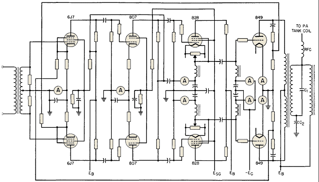
In the diagram of Fig. 157, the first two stages have current feedback, and so initial tests were made with the circuit shown. But overall voltage feedback from the modulator plates back to the 6J7 grids was not applied until the amplifier was first tested without it. Then resistors from which feedback is derived were adjusted to produce the feedback voltage necessary to give the required performance. The carrier power amplifier was completely adjusted before modulation was applied. Percentage of modulation was measured by the increase of carrier output current when modulation was applied. Inductance RFC and capacitor C1 maintain the modulator load constant at high frequencies. C2 in this circuit is the audio coupling capacitor. Separate meters are provided to measure the plate current of each driver and modulator tube, so that bias may be adjusted for the same plate current on each side. Proper operation is predicated on amplifier stability, which often is not obtained when power is first turned on. Local or parasitic oscillations may easily occur as a result of natural resonance of circuit elements or even in connections and tube electrodes. These must be detected and eliminated by corrective measures which apply to the trouble. Some of these troubles may be caused by long leads, especially in the grid circuit. Tubes may require resistors in the plate and grid leads to damp out parasitic oscillations. Resistors are used in this manner in the amplifier shown in Fig. 157. Coils in circuits with widely different voltages should not be coupled closely, because regeneration may result. In circuits with high voltage, and therefore large capacitive currents, it may be necessary to add shielding to prevent stray pick-up from one stage to another. In push-pull amplifiers, if some circuit element is unbalanced, it may give rise to a push-push oscillation which can be eliminated by better balance, or by decoupling the tube plates at the unwanted frequency. If insufficient bypass capacity is used on plate or bias supplies, interstage coupling may occur at low frequencies. The frequency may be less than 1 cycle per second. This kind of instability is known as "motor-boating." Operating tubes so that some electrode becomes a negative resistance during a portion of the cycle may give rise to oscillations which cannot be prevented except by avoidance of the cause, or by some power-absorbing circuit which does not affect normal operation. The elimination of such trouble requires much testing time and skill, but it must be done before performance tests are made.
|
||||
Home  Amplifier Circuits Amplifier Circuits  Amplifier Tests Amplifier Tests |
||||
Last Update: 2011-02-06


