| Electronic Transformers and Circuits is a free introductory textbook on transformers and related circuits. See the editorial for more information.... |

|

Home  Higher-Frequency Transformers Higher-Frequency Transformers  Capacitance Evaluation Capacitance Evaluation |
||||||||||||||||||


|
||||||||||||||||||
Capacitance Evaluation
It will be assumed that the right ends of both windings are connected to ground (or core) through large capacitances, as shown dotted, so that the right ends are at substantially the same a-c potential. Primary capacitance C1 is composed of many small incremental capacitances Cp, and secondary C2 of many small incremental capacitances CS , each of which has a different voltage across it. Likewise, many small incremental capacitances Ca exist between primary and secondary, which have different potentials across them. If the transformer is step-up,
If the transformer is step-down,
If the ratio is 1:1,
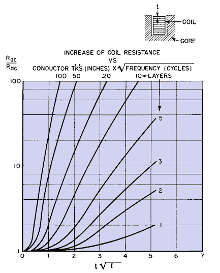
For transformers with opposite angular rotations of primary and secondary windings, or with opposite traverse directions (but not both), minus signs in the factors (Np - NS)2/NP2 and (Ns - Np)2/Ns2 in equations 97 and 98 become positive; there is no other change. For transformers with both angular rotations and traverse directions opposite there is no change at all in these equations. If there is a shield between primary and secondary, omit terms containing Ca in these equations, and make ∑CS and ∑CP include the capacitance of secondary and primary to shield, respectively. ∑CS is the measurable capacitance of the short-circuited secondary to core, and ∑CP that of the short-circuited primary to core. In push-pull amplifier transformers, the secondary winding is interleaved between two primary halves. The rotational directions of winding and traverse are important, as they affect not only effective capacitance but also plate-to-plate coupling. It is usually best to have all windings with the same rotational direction and traverse, and to connect the primary halves externally. Winding resistance increases with frequency because of eddy currents in the larger wire sizes, and copper loss increases proportionately. Formulas for single-layer coils are given in handbooks.(1) Eddy-current resistance of layer-wound coils in deep open slots is plotted in Fig. 167 as a function of conductor thickness, frequency, and number of coil layers; it approximates the increase of winding resistance in a transformer.(2)
|
||||||||||||||||||
Home  Higher-Frequency Transformers Higher-Frequency Transformers  Capacitance Evaluation Capacitance Evaluation |
||||||||||||||||||
Last Update: 2011-02-17


