| Electronic Transformers and Circuits is a free introductory textbook on transformers and related circuits. See the editorial for more information.... |

|

Home  Higher-Frequency Transformers Higher-Frequency Transformers  Mutual Inductance Mutual Inductance |
||||||||||||||||||


|
||||||||||||||||||
Mutual Inductance
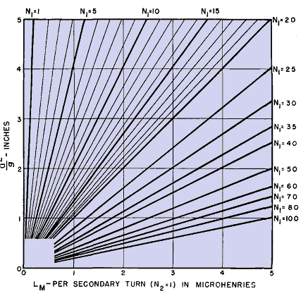
It is evident from equation 101 that the secondary voltage depends upon the mutual inductance between the coils. Mutual inductance can be calculated by formulas which depend upon the geometric configuration of the coils. If the coils are arranged concentrically, as shown in either (a) or (b) of Fig. 174, the mutual inductance of the coils can be found from
where N1 = primary turns and N2 = secondary turns.
All dimensions are in inches. For most purposes, the bracketed portion of this formula is approximately unity, and it has been plotted in Fig. 175 for a single-turn secondary.
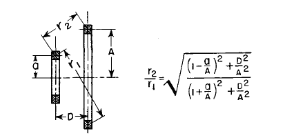
If the coils are arranged coaxially as in Fig. 176, approximate values of mutual inductance are found as follows:
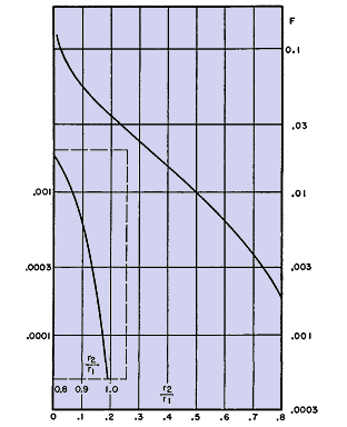
In this formula all dimensions are in inches and the mutual inductance is in microhenrys. The factor F can be conveniently found in Fig. 177.
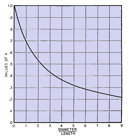
Self-inductance of single-layer coils is
where a = mean coil radius in inches Equations 105, 106, and 107 are based on equations 192, 187, and 153 in Natl. Bur. Standards Circ. 74.
Receiver intermediate-frequency tuned transformers generally have coaxial coils. If the wire is more than 0.005 in. in diameter, it is commonly subdivided into several strands in the type of cable known as Litzendraht, to reduce losses and increase Q. In transmitters, the size of the coils becomes much larger, and concentric coils are employed. The wire used is Litzendraht at 600 kc or lower frequency, and may contain many strands for carrying heavy currents. At higher frequencies the wire is of solid or tubular section.
|
||||||||||||||||||
Home  Higher-Frequency Transformers Higher-Frequency Transformers  Mutual Inductance Mutual Inductance |
||||||||||||||||||
Last Update: 2011-01-24


