| Electronic Transformers and Circuits is a free introductory textbook on transformers and related circuits. See the editorial for more information.... |

|

Home  Pulse and Video Transformers Pulse and Video Transformers  Square Waves Square Waves |
||||


|
||||
Square Waves
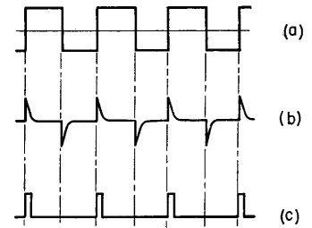
Square waves can be generated in several ways: sometimes from sine waves by driving a tube into the diode region each cycle. The plate circuit voltage wave form is then different from that of the grid voltage because the round top of the sine wave has been removed. By repeating this process (called clipping) in several stages, it is possible to produce very square waves, alternately plus and minus, like those of Fig. 225(a). If a voltage having such a wave form is applied across a capacitor, it causes current to flow in the capacitor only at the vertical edges, as in Fig. 225(b).
If a voltage proportional to this current is then successively amplified and clipped at the base, it results in the wave form of Fig. 225 (c). Here the negative loops are assumed to be missing, as they could be after single-side amplification. The wave is square but of much shorter duration than in Fig. 225(a), and the interval between pulses greatly exceeds the pulse duration. The pulse duration is usually referred to as the pulse width, and the frequency at which the pulses occur is called the repetition rate and is expressed as pulses per second (pps). Common pulse widths lie between 0.5 and 10 microseconds; the intervals between pulses may be between 10 and 1,000 times as long as the pulse width. These values are representative only, and in special cases may be exceeded several-fold. The general wave shape of Fig. 225 (c), with short pulse duration compared to the interval between pulses, is the main subject of this chapter. The ratio of peak to average voltage or current may be very high, and the rms values appreciably exceed average in such pulses. There are two ways in which the response of any circuit to a square wave can be found. The first of these consists in resolving the pulse into a large number of sine waves of different frequencies, finding the response of the circuit to each frequency and summing up these responses to obtain the total response. This can be formulated by a Fourier integral, but for most circuits the formulation is easier than the solution. An approximation to this method is the arbitrary omission of frequency components having negligible amplitude, and calculation of the circuit response to the relevant frequencies. This approximation has two subjective criteria: the number of frequencies to be retained, and the evaluation of the frequency components for which the circuit has poor response. The second method, which will be used here, consists in finding the transient circuit response to the discontinuities at the front and trailing edges of the square wave. It is possible to reduce the transformer to a circuit amenable to transient analysis, without making any more assumptions than would be necessary for practical design work with the Fourier method. The transient method has the advantage of giving the total response directly, and it can be plotted as a set of curves which are of great convenience to the designer. The major assumption is that one transient disappears before another begins. If good square wave response is obtained, this assumption is justified. Analyses are given of the influence of iron-core transformer and choke characteristics on pulse wave forms. In all these analyses the transformer or choke is reduced to an equivalent circuit; this circuit changes for different wave forms, portions of a wave form, and modes of operation. Initial conditions, resulting formulas, and plots of the formulas for design convenience are given for each case. Formulas may be verified by the methods of operational calculus.
|
||||
Home  Pulse and Video Transformers Pulse and Video Transformers  Square Waves Square Waves |
||||
Last Update: 2011-01-24


