| Electronic Transformers and Circuits is a free introductory textbook on transformers and related circuits. See the editorial for more information.... |

|

Home  Pulse and Video Transformers Pulse and Video Transformers  Transformer-Coupled Pulse Amplifiers Transformer-Coupled Pulse Amplifiers |
||||||||


|
||||||||
Transformer-Coupled Pulse Amplifiers
The analysis here given is for a square- or flat-topped pulse impressed upon the transformer by some source such as a vacuum tube, a transmission line, or even a switch and battery.
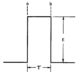
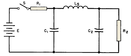
The equivalent circuit for such an amplifier is given in Fig. 228. At least this is the circuit which applies to the front edge a of the pulse shown in Fig. 226 as rising abruptly from zero to some steady value E. This change is sudden, so that the transformer OCL can be considered as presenting infinite impedance to such a change, and is omitted in Fig. 228.
Transformer leakage inductance, though, has an appreciable influence and is shown as inductance Ls in Fig. 228. Resistor R1 of Fig. 228 represents the source impedance; transformer winding resistances are generally negligible compared to the source impedance. Winding capacitances are shown as C1 and C2 for the primary and secondary windings, respectively. The transformer load resistance, or the load resistance into which the amplifier works, is shown as R2. All these values are referred to the same side of the transformer. Since there are two capacitance terms C1 and C2, it follows that, for any deviation of the transformer turns ratio from unity, one or the other of these becomes predominant. Turns ratio and therefore voltage ratio affect these capacitances, as discussed in Chapter 5; for a step-up transformer, C1 may be neglected, and, for a step-down transformer, C2 may be neglected. The discussion here will be confined first to the step-up case.
|
||||||||
Home  Pulse and Video Transformers Pulse and Video Transformers  Transformer-Coupled Pulse Amplifiers Transformer-Coupled Pulse Amplifiers |
||||||||
Last Update: 2011-01-24


