| Electronic Transformers and Circuits is a free introductory textbook on transformers and related circuits. See the editorial for more information.... |

|

Home  Pulse and Video Transformers Pulse and Video Transformers  Non-Linear Loads Non-Linear Loads |
||||||


|
||||||
Non-Linear Loads
The role played by leakage inductance and distributed capacitance in determining pulse shape has been mentioned in Front-Edge Response and Trailing-Edge Response. It has been shown that the first effect is a more or less gradual slope on the front edge of the pulse, and that the second effect consists of oscillations superposed upon the voltage back-swing following the cessation of the pulse. Consider the additional influence of non-linear loads upon the first effect, that is, upon the pulse front edge.
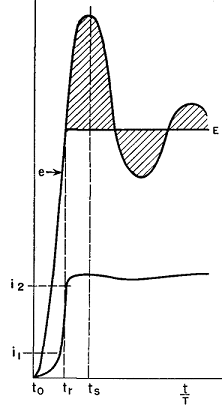
(a) Load and source impedances are linear. (b) Leakage inductance can be regarded as "lumped." (c) Winding capacitance can be regarded as "lumped." Assumptions (b) and (c) are approximately justified. Pulses effectively cause the coils to operate beyond natural resonance, like the higher-frequency operation of r-f coils in R-F Chokes. The distributed nature of capacitance and leakage inductance, as well as partial coil resonance, may cause superposed oscillations which require correction. But the general outline of output pulse shape is determined by low-frequency leakage inductance and capacitance. Assumption (a) may be a serious source of error, for load impedances are often non-linear. Examples are triodes, magnetrons, or grid circuits driven by pulse transformers. In a non-linear load with current flowing into the load at a comparatively constant voltage, the problem is chiefly that of current pulse shape. First assume that no current flows into this load for such time as it takes to reach steady voltage E. During this first interval, the transformer is unloaded except for its own losses, and is oscillatory. After voltage E is reached, the current rises rapidly at first and then more slowly, as determined by the new load R2. The sudden application of load at voltage E damps out the oscillations which would exist without this load, and furnishes two conditions for finding the initial current. A rigorous solution of the problem involves overlapping transients and is complicated. The problem can be simplified by assuming that the voltage pulse has a flat top E. When the pulse voltage reaches E, capacitance C2 ceases to draw current. At the instant tr (Fig. 243) when voltage E is first reached, the current in Ls which was drawn by capacitance C2 flows immediately into the load.
Also since the voltage was rising rapidly at instant tr, the energy which would have resulted in the first positive voltage loop (shown shaded in Fig. 243) must be dissipated in the load. The remaining oscillations also are damped. Prior to the time tr all the current through Ls flowed into C2. The value of this current is C2 de/dt. Therefore we may find the slope of the appropriate front-edge voltage curve and multiply by the transformer capacitance to obtain the initial current. Unloaded transformer front edge means small k1 in Figs. 230 and 231. The front-edge slope at voltage E is given in Fig. 244, the ordinates of which are (T de/E)/dt, with E corresponding to the Ea of Fig. 230. Ordinates of Fig. 244 are multiplied by C2E/T to find the initial load current.
Few non-linear loads have absolutely zero current up to the time that voltage E is reached, and the foregoing assumptions are thus approximate. In spite of this, the following procedure gives fair accuracy. (a) Find the initial capacitance current as just outlined. (b) Estimate the current at which the load e-i curve departs from a straight line (i1, in Fig. 243). (c) Add currents (a) and (b). This gives i2 (Fig. 243), as the total initial current. Pulse current continues to rise beyond the value i2 if the initial current value just found is less than the final operating current corresponding to the voltage E; it will droop if the initial current is higher than the load current at voltage E. To obtain constant current over the greater part of the pulse width, i2 should equal the load current at voltage E. When this equality does not exist, the rate of rise or droop is determined by transformer leakage inductance, source impedance, and load resistance. Where the mode of operation depends upon the rate of voltage rise, as it does in some magnetrons, the initial current may drop off to nearly zero before the main current pulse starts. When there is negligible initial current i1 the condition for a good current pulse is E/i2 ≈ √(LS/C2), where Ls is the leakage inductance. At the end of the pulse, when the source voltage is reduced to zero (point b, Fig. 226), the circuit reverts to that shown on Fig. 235, but the transformer loses all the load except its own losses. Since by this time it has drawn exciting current, the higher values of A in the back-swing curves apply. Backswing amplitudes with non-linear loads are complicated and can be predicted only approximately. A procedure for line-type pulsers is given in Pulse Circuits.
|
||||||
Home  Pulse and Video Transformers Pulse and Video Transformers  Non-Linear Loads Non-Linear Loads |
||||||
Last Update: 2011-01-24


