| Electronic Transformers and Circuits is a free introductory textbook on transformers and related circuits. See the editorial for more information.... |

|

Home  Pulse Circuits Pulse Circuits  False Echoes after Main Pulse False Echoes after Main Pulse |
|||||||||||||||||||||||


|
|||||||||||||||||||||||
False Echoes after Main Pulse
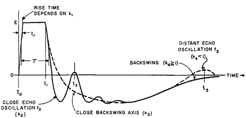
The low-frequency backswing oscillation or axis is affected by CN only while it is still in the circuit. When thyratron conduction ceases (soon after the trailing edge becomes negative) CN is cut out of the circuit. Once this happens, the presence or absence of distant echoes is determined only by CD in combination with Le and Re. Moreover, if CN >> CD, close echoes are also determined by CD and L'N, regardless of whether or not the thyratron is conducting during the close-echo interval. Both low- and high-frequency oscillation amplitudes depend on the amount of resistance in the circuit. At instant t1 this resistance is RM, the magnetron resistance E/i2 (Fig. 243), in comparison with which the transformer core-loss equivalent resistance Re is negligibly high. After the magnetron ceases conducting, only Re remains. During the trailing-edge interval, circuit resistance varies from RM to Re. Resistances RM and Re may be replaced by their geometric mean R1 during the trailing-edge interval and the part of the backswing immediately following. This applies to both low- and high-frequency backswing oscillations during the interval t2-t1 (Fig. 254). The low-frequency or long-term axis of backswing may then be found from values of parameter k3 determined by Le, CD, and Rr, as indicated in Fig. 235. If the oscillations are damped out, the impedance ratio still determines wave shape. This ratio is designated k1, k2, k3, or k4, depending on the portion of the pulse as indicated in Fig. 254. If PFN produces an essentially square wave, front-edge wave shape at the magnetron is determined by impedance ratio
It may be shown(1) that if k1 = 0.5 the magnetron voltage and current rise without oscillations to final value at tr = 1.6 √(LsCd). This k1 has little influence on the trailing edge because Ls is usually small compared to Le. Oscillations occurring close to the trailing edge of the pulse are of frequency f2 (determined by L'NC'D, where C'D = CDCN/(CD + CN), L'N is the sum of the transformer leakage and PFN inductance), and of amplitude determined by
This amplitude is superposed on the backswing as an axis, which, if oscillatory, has frequency f3 determined by LeC'D. Since one purpose of good pulser design is the elimination of false echoes, the backswing axis considered here is always non-oscillatory. Assuming the thyratron is non-conducting for most of the backswing interval, the condition for non-oscillatory backswing is
for the close part of the backswing and
for the distant part where Le is the OCL at time t1 and J is the ratio of low-frequency core permeability to pulse permeability. If
and
then
because generally
So, if the pulser is designed to prevent distant echoes, k4 ≥ 1 and k3 is several times the value of k4. Time intervals influenced by these impedance ratios are illustrated in Fig. 254. In general, for a good pulse, the close part of the backswing axis follows a non-oscillatory pattern of relatively high-impedance ratio, such as those shown on Fig. 235 for k3 > 1. The general effect of pulse transformer magnetizing current is to depress the backswing axis. Magnetizing current does not affect the criterion for absence of false echoes k4 > 1; hence a high ratio J is helpful in eliminating close echoes. The ratio A of magnetizing current to load current is much less for the close echo than for the distant echo because R1 is less than Re. Close echo Δ is approximated by
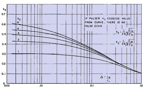
To prevent close echo, the first positive peak of oscillation should be no greater than the negative backswing axis voltage at instant t2. Backswing axis voltage may be equated to the amplitude of the first positive oscillation peak at time t2 in Fig. 254. This equation leads to a transcendental relation between k2, k3, and Δ, which is plotted in Fig. 255.(2)
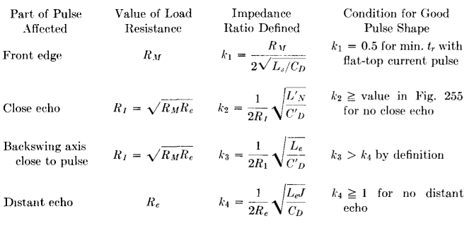
It will be noted that all values of k2 in Fig. 255 are less than unity. Hence, under the conditions here assumed, there is always a certain amount of high-frequency oscillation superposed on the back-swing axis. But, if k2 is greater than the value given by Fig. 255, there is no false close echo. Because of the approximation represented by equivalent resistance RI, to prevent false echoes it is best if k2 exceeds the curve value substantially. For convenience, the various impedance ratios are tabulated in Table XVII.
Table XVII. Pulser Impedance Ratios
|
|||||||||||||||||||||||
Home  Pulse Circuits Pulse Circuits  False Echoes after Main Pulse False Echoes after Main Pulse |
|||||||||||||||||||||||
Last Update: 2011-02-17


