| Electronic Transformers and Circuits is a free introductory textbook on transformers and related circuits. See the editorial for more information.... |

|

Home  Pulse Circuits Pulse Circuits  Line-Type Radar Pulsers Line-Type Radar Pulsers |
||||||


|
||||||
Line-Type Radar Pulsers
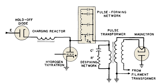
Figure 252 is the schematic diagram of a line-type pulser or modulator. This pulser is of the variety known as d-c resonant charging, with hold-off diode. The operation of the pulser is as follows:
The pulse transformer load is the magnetron, which is operated with high negative potential on the cathode. A double winding is provided on the pulse transformer secondary to permit filament current to flow into the magnetron filament. The reactances of the pulse-forming network and the charging reactor at their resonant frequency are high compared to the circuit equivalent series resistance. Therefore, the pulse-forming network charges up to a voltage 2E, where E is the d-c supply voltage. Negligibly small voltage appears on the pulse transformer and magnetron during the charging interval. After the pulse-forming network has charged up fully, it is prevented from discharging back through the d-c source by the hold-off diode. At some subsequent instant, a trigger voltage on the grid of the hydrogen thyratron causes the thyratron to conduct and permits the pulse-forming network to discharge through the very low internal resistance of the thyratron. The sudden discharge of current through the thyratron causes a voltage wave to start down the pulse-forming network as in Fig. 253.
This voltage is an inverted step function with a value (2E - E) = E. Initial voltage 2E on this network is divided equally between the network and the pulse transformer primary, and produces pulse voltage E, of duration τ. The pulse width τ is the length of time that the pulse takes to travel down the pulse-forming network (PFN) and back. After time t1 the circuit is ready to charge slowly again through the charging reactor. Magnetron current and voltage rise at the pulse leading edge in general accordance with the explanation of Non-Linear Loads, but sometimes "despiking" network R'C' is included to reduce current oscillations. In this pulser, the magnetron equivalent resistance RM (referred to the pulse transformer primary) is equal to ZN, the pulse-forming network impedance. If the magnetron circuit opens during pulser operation, voltage applied to the pulse transformer primary is doubled. This may cause insulation failure if the open circuit continues. For this reason, spark gaps are often provided on pulse transformers in line-type pulsers.
|
||||||
Home  Pulse Circuits Pulse Circuits  Line-Type Radar Pulsers Line-Type Radar Pulsers |
||||||
Last Update: 2011-01-24


