| Electronic Transformers and Circuits is a free introductory textbook on transformers and related circuits. See the editorial for more information.... |

|

Home  Pulse Circuits Pulse Circuits  Magnetic Pulse Generators Magnetic Pulse Generators |
||||||||||||


|
||||||||||||
Magnetic Pulse Generators
In Magnetic Amplifiers it was seen that thyratron operation can be approximated by self-saturating magnetic amplifiers. This fact points to a saturable reactor to replace the hydrogen thyratron in the pulser of Fig. 252. Several factors militate against the direct substitution of saturable reactors for thyratrons:
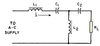
1. Departure of core material from sharp rectangularity interferes with steep pulse voltage rise. 2. Saturated value of inductance interferes with large current flow needed during pulse. 3. Reactors are a-c devices; hence a-c charging must be used. This limits the choice of PRF. Despite these difficulties, saturable reactors have been used successfully in pulsers. Low power pulses may be formed by use of the circuit of Fig. 202. Reactor L1 is linear and resonates with C1 at the supply frequency. Resonance therefore tends to maintain current i sinusoidal in wave form. Current i is large enough to saturate reactor L2, which has rectangular B-H loop core material. Twice each cycle current i passes through zero, and near these current zeros L2 inductance becomes large. This large inductance forces most of current i instantaneously into C2 and RL, and builds up a comparatively large peak voltage across RL. Such pulses are peaked in wave shape and alternate in polarity twice each cycle. Pulse durations of less than 0.1 microsecond have been obtained with this circuit. Owing to the large interval of time during which i is large, and not producing pulses, the power output is limited to small values.
In Fig. 262 the voltage across L2 at a given line frequency f is nearly proportional to the saturation flux density Bs of the core for rectangular loop material. If the core area is Ac and turns N in L2, then this voltage is, neglecting losses,
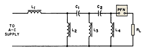
where Θs/2 is the angle, starting from zero, at which saturation is reached, as in Fig. 193 (p. 247). If Θs is very small, and 2μ/ω >> RLC2 >> Θs/ω, substantially all of es appears across RL. Higher power may be obtained from cascaded stages as in Fig. 263.
Reactor L1 is linear and resonates with C1 at the supply frequency. Reactors L2, L3 and L4 are saturable; bias windings are used, but not shown. Suppose that L3 and L4 are initially unsaturated, and L3 is saturated. C1 charges in series with L1 and L3. As the voltage across L2 reaches maximum, L2 saturates and discharges C1. Discharge current causes L3 to become unsaturated and L4 saturated; then C2 charges until L3 saturates again. As the wave proceeds towards RL both charge and discharge times become successively shorter. Pulse duration in each stage is determined by the saturated value of inductance and associated C. In the last stage, the pulse is shaped by PFN to the desired duration and flatness at the top. As this sequence is repeated once each cycle, the line current is not sinusoidal, so a line capacitor is useful for supplying the current harmonics. One modification of this circuit is the use of saturating transformers instead of reactors in order to provide the stepped-up voltage necessary for magnetron operation. With a magnetron, RL is replaced by a pulse transformer primary winding. In another modification saturable reactors are the series elements and capacitors the shunt.(1)
|
||||||||||||
Home  Pulse Circuits Pulse Circuits  Magnetic Pulse Generators Magnetic Pulse Generators |
||||||||||||
Last Update: 2011-02-17


