| The ebook FEEE - Fundamentals of Electrical Engineering and Electronics is based on material originally written by T.R. Kuphaldt and various co-authors. For more information please read the copyright pages. |

|
Home  DC Divider Circuits and Kirchhoff's Laws Potentiometer DC Divider Circuits and Kirchhoff's Laws Potentiometer |
|||


|
  |
||
|
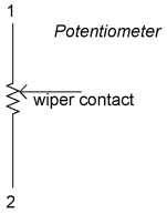
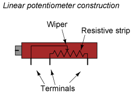
PotentiometerOne device frequently used as a voltage-dividing component is the potentiometer, which is a resistor with a movable element positioned by a manual knob or lever. The movable element, typically called a wiper, makes contact with a resistive strip of material (commonly called the slidewire if made of resistive metal wire) at any point selected by the manual control:
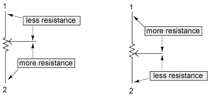
The wiper contact is the left-facing arrow symbol drawn in the middle of the vertical resistor element. As it is moved up, it contacts the resistive strip closer to terminal 1 and further away from terminal 2, lowering resistance to terminal 1 and raising resistance to terminal 2. As it is moved down, the opposite effect results. The resistance as measured between terminals 1 and 2 is constant for any wiper position.
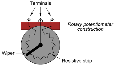
Shown here are internal illustrations of two potentiometer types, rotary and linear:
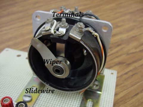
Some linear potentiometers are actuated by straight-line motion of a lever or slide button. Others, like the one depicted in the previous illustration, are actuated by a turn-screw for fine adjustment ability. The latter units are sometimes referred to as trimpots, because they work well for applications requiring a variable resistance to be "trimmed" to some precise value. It should be noted that not all linear potentiometers have the same terminal assignments as shown in this illustration. With some, the wiper terminal is in the middle, between the two end terminals. The following photograph shows a real, rotary potentiometer with exposed wiper and slidewire for easy viewing. The shaft which moves the wiper has been turned almost fully clockwise so that the wiper is nearly touching the left terminal end of the slidewire:
Here is the same potentiometer with the wiper shaft moved almost to the full-counterclockwise position, so that the wiper is near the other extreme end of travel:
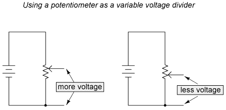
If a constant voltage is applied between the outer terminals (across the length of the slidewire), the wiper position will tap off a fraction of the applied voltage, measurable between the wiper contact and either of the other two terminals. The fractional value depends entirely on the physical position of the wiper:
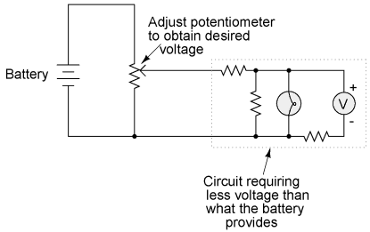
Just like the fixed voltage divider, the potentiometer's voltage division ratio is strictly a function of resistance and not of the magnitude of applied voltage. In other words, if the potentiometer knob or lever is moved to the 50 percent (exact center) position, the voltage dropped between wiper and either outside terminal would be exactly 1/2 of the applied voltage, no matter what that voltage happens to be, or what the end-to-end resistance of the potentiometer is. In other words, a potentiometer functions as a variable voltage divider where the voltage division ratio is set by wiper position. This application of the potentiometer is a very useful means of obtaining a variable voltage from a fixed-voltage source such as a battery. If a circuit you're building requires a certain amount of voltage that is less than the value of an available battery's voltage, you may connect the outer terminals of a potentiometer across that battery and "dial up" whatever voltage you need between the potentiometer wiper and one of the outer terminals for use in your circuit:
When used in this manner, the name potentiometer makes perfect sense: they meter (control) the potential (voltage) applied across them by creating a variable voltage-divider ratio. This use of the three-terminal potentiometer as a variable voltage divider is very popular in circuit design. PotentiometerShown here are several small potentiometers of the kind commonly used in consumer electronic equipment and by hobbyists and students in constructing circuits: 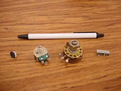
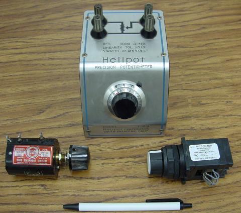
The smaller units on the very left and very right are designed to plug into a solderless breadboard or be soldered into a printed circuit board. The middle units are designed to be mounted on a flat panel with wires soldered to each of the three terminals. Here are three more potentiometers, more specialized than the set just shown: Potentiometer, precision
The large "Helipot" unit is a laboratory potentiometer designed for quick and easy connection to a circuit. The unit in the lower-left corner of the photograph is the same type of potentiometer, just without a case or 10-turn counting dial. Both of these potentiometers are precision units, using multi-turn helical-track resistance strips and wiper mechanisms for making small adjustments. The unit on the lower-right is a panel-mount potentiometer, designed for rough service in industrial applications.
|
|||
| Home DC Divider Circuits and Kirchhoff's Laws Potentiometer |
|
||

Last Update: 2010-12-01