| Practical Physics is a free textbook on basic laboratory physics. See the editorial for more information.... |
|
Home  Electricity Carey Foster's Method of Comparing Resistances Electricity Carey Foster's Method of Comparing Resistances |
||||||


|
  |
|||||
Carey Foster's Method of Comparing Resistances
The B.A. wire bridge just described is most useful when it is required to determine the difference between two nearly equal resistances of from one to ten ohms in value. The method of doing this, which is due to Professor Carey Foster, is as follows. Let R and s be the two nearly equal resistances to be compared; P and Q two other nearly equal resistances, which should, to give the greatest accuracy, not differ much from R and S. We do not require to know anything about P and Q except that they are nearly equal. It is convenient to have them wound together on the same bobbin, for then we can be sure that they are always at the same temperature.
Place R and s in the gaps AM, BM' of the bridge, and P and Q in the gaps AD and DB respectively. Let a and b, as before, be the lengths of the bridge-wire on either side of C when the galvanometer needle is in equilibrium. Let X, Y be the unknown resistances of the two strips MN and M'N'. Fig. 72 shows the arrangement. Then, if σ be the resistance of one centimetre of the bridge-wire, we have
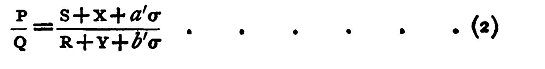
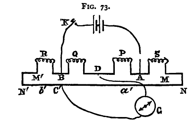
Interchange the position of R and S and determine another position C (fig. 73), for the galvanometer contact in which there is no deflexion. Let a', b' be the corresponding values of a and b. Then
And by adding unity to each side we have, from equations (1) and (2)
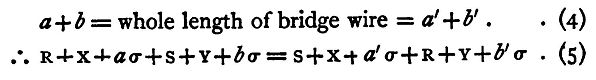
Also
Hence from (3)
Now (a'-a)σ is the resistance of a portion of the bridge wire equal in length to the distance through which the sliding-piece has been moved. This distance can be measured with very great accuracy, and thus the difference of the resistances of the two coils can be very exactly deter, mined.
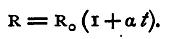
At the three points C, N, N', we have contacts of two dissimilar metals. These points are probably at different temperatures - the observer's hand at c tends to raise its temperature - and a difference of temperature in a circuit of different metals will, it is known, produce a thermoelectric current in the circuit This current will, under the circumstances of the experiment, be very small; still, it may be a source of error. The best method of getting rid of its effects is to place a commutator in the battery circuit, and make two observations of each of the lengths a and a', reversing the battery between the two. It can be shown that the mean of the two observations gives a value free from the error produced by the thermo-electric effect Again, a variation in the temperature of a conductor produces an alteration in its resistance. For very accurate work it is necessary to keep the coils R and s at known temperatures. This is generally done by means of a water-bath, in which the coils are immersed. It has been found that for most of the metals, at any rate within ordinary limits of temperature, the change of resistance per degree of temperature is very nearly constant, so that if R be the resistance of a coil at temperature t° C., R0 its resistance at 0°, and α the coefficient of increase of resistance per degree of temperature, we have
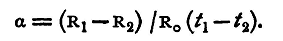
Carey Foster's method is admirably adapted for finding this quantity α. The standard coil S is kept at one definite temperature, and the values of the difference between its resistance and that of the other coil are observed for two temperatures of the latter. Let these temperatures be t1 and t2, and the corresponding resistances R1 and R2; then we have
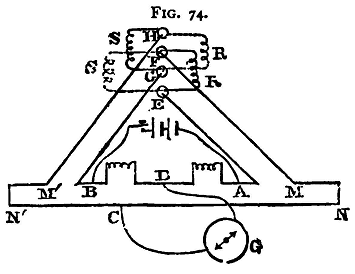
The observations have given us the values of R1-S and R2-S with great accuracy, and from them we can get R1-R2; an approximate value of R0 will be all that is required for our purpose, for it will be found that a is a very small quantity, and we have seen (p. 44) that we may without serious error employ an approximate value in the denominator of a small fraction. Whenever precautions are requisite to maintain the coils at a uniform temperature, the interchanging of the coils R, s is a source of difficulty with the ordinary arrangements. Time is lost in moving the water-jackets in which the coils are immersed, and the temperature may vary. The contacts, moreover, are troublesome to adjust. To obviate this, among other difficulties, a special form of bridge was devised by Dr. J. A. Fleming, and described in the 'Proceedings of the Physical Society of London,' vol. iii. The ordinary bridge may be easily adapted to an arrangement similar to Fleming's, as follows. EGFH (fig. 74) are four mercury cups; E and F are connected by stout copper rods with A and M, G and H with B and M' respectively.
For the first observation the electrodes of R are placed in E and F being held in their position by weights or spring clamps, while the electrodes of s are in G and H. For the second observation the electrodes of R are placed in G and H, those of s in E and F, as shown by the dotted lines. This interchange is easily effected. The water jackets need not be displaced; the coils can readily be moved in them. The connections AE, MF, &c., may conveniently be made of stout copper rod, fastened down to a board of dry wood, coated with paraffin. To make the mercury cups the ends of these rods are turned up through a right angle and cut off level. They are then amalgamated and short pieces of india-rubber tubing are slipped over them, and tied round with thin wire; the india-rubber tubing projects above the rod, and thus forms the cup. The other ends of the rods are made to fit the binding screws of the ordinary bridge.(1)
|
||||||
| Home Electricity Carey Foster's Method of Comparing Resistances |
|
|||||


Last Update: 2011-03-27