| Practical Physics is a free textbook on basic laboratory physics. See the editorial for more information.... |

|
Home  Electricity The British Association Wire Bridge Electricity The British Association Wire Bridge |
||


|
  |
|
The British Association Wire Bridge
The apparatus used for measuring resistances by the Wheatstone-bridge method frequently takes another form. The theory of the method is of course the same as when the box is employed, but instead of varying the resistance S, the ratio P/Q is made capable of continuous alteration. The conductors BC, CA of figure 64 are two portions of a straight wire of platinum-silver or German-silver, or some other material of a high specific resistance, which is carefully drawn so as to have a uniform cross-section, the resistance of any portion of such a wire being proportional to its length. The ratio of the resistances P/Q will be the ratio of the two lengths AC/BC.
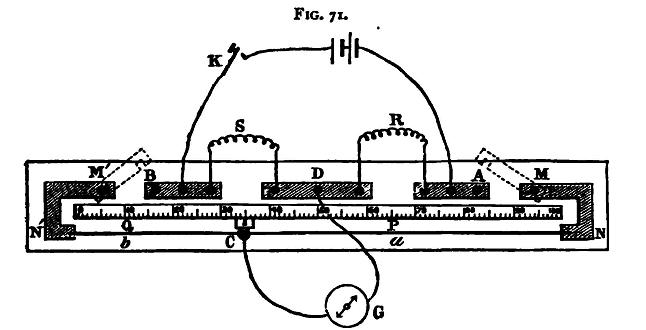
A scale, usually divided to millimetres, is fixed parallel to the wire; the ends of the wire A and B coincide with the extremities of the scale; and the position of the point C, at which the contact is made, can be read by means of a mark on the sliding-piece. The ends of this wire are fixed to stout copper pieces, by means of which connection is made with the resistances R and S. These copper strips are so thick that for many purposes their resistance may be neglected when compared with that of the wire ACB. The apparatus usually takes the form shown in fig. 71. The strips NMA, N'M'B are the stout copper pieces just referred to. It will be noticed that there are gaps left between M and A, M' and B; their purpose will be explained shortly (p. 454). When the bridge is used as described above, these two gaps are closed by two strips of copper, shown by dotted lines in the figure, which are screwed tightly down to the fixed copper pieces. The wire R, whose resistance is required, and S, the standard, are electrically connected with the apparatus, either by means of binding screws or of mercury cups, as may be most convenient; binding screws are also provided for the battery and galvanometer wires.
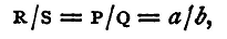
To make a determination of the value of R, close the gaps AM and BM' and connect the resistances, battery, and galvanometer, as shown in the figure. Close the battery circuit by the key K. Move the jockey c until a position is found for it, such that no deflexion is produced in the galvanometer on making contact at C. Let a and b be the lengths of the two pieces of the bridge wire on either side of C. Then we have
and
The apparatus may conveniently be used to find the specific resistance of the material of which a wire is composed. For if R be the resistance, and ρ the specific resistance of a wire of length l and uniform circular cross-section of diameter d, then the area of the cross-section is d2π/4 and we have
so that
The value of R can be found by the method just described. The length of the wire may be measured with a steel tape, or other suitable apparatus, and the diameter d can be determined by the aid of the screw gauge. For great accuracy this method of finding the diameter may not be sufficient. It may be more accurately calculated from a knowledge of the mass, length, and density of the wire (see §8). The determination of R by the method just described is not susceptible of very great accuracy. The position of C cannot be found with very great exactness, and an error in this will produce very considerable error in the result. It can be shown as follows that the effect of an error x in the position of C produces least effect in the result when C is the middle point of the wire. For let c be the whole length of the wire; then we. have found that
Suppose that an error x has been made in the position of c, so that the true value of a is a+x. Then the true value of R is R+X, say, where
Hence if we neglect terms involving x2 we have
Hence
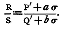
Now it is shown in books on Algebra that a(c-a) is greatest when a = c-a, that is, when a = c/2, or c is at the middle point of the bridge-wire; and in this case the ratio of X to R, that is, the ratio of the error produced by an error x in a to the resistance measured, is least when C is at the middle point. Thus the standard chosen for s should have approximately the same value as R. This may be conveniently arranged for by using a resistance-box for S and taking out plugs until the adjusted position of C is near the middle of the wire. But even with this precaution the method is far from sensitive; the resistance of the wire NN' is probably very small compared with the resistances R and S. Nearly all the current flows directly through the wire, and very little through the coils R and S. The greatest possible difference of potential between C and D is small, and the deflexion of the galvanometer will always be small. To remedy this two other resistance coils are inserted in the gaps AM and BM', the copper strips being removed. Suppose their resistances respectively are P' and Q', and suppose that the value of R is known approximately, or has been found from a rough observation as above. The values of P', Q' must be such the ratio of P' to Q' does not differ much from that of R to S. Suppose that when the position of equilibrium is found the lengths of wire on either side of C are a and b, and that the resistance of a unit length of the wire is known to be σ. Then, if we neglect the resistances of the copper strips MN and M'N' - these will be exceedingly small, and may be neglected without sensible error - the value of P will be P'+aσ, and that of Q, Q'+bσ, and we have
The value of R is thus determined, and it can be shown that the error in the result produced by a given error in the position of C is much less than when there is no resistance between A and M, B and M. This method involves a knowledge of σ, the resistance of a centimetre of the bridge-wire. To find this the resistance of the whole wire may be measured with a Post-Office box, or otherwise, and the result divided by the length of the wire in centimetres. Another method of determining σ will be given in the next section. Moreover, since aσ and bσ are small compared with P' and Q', it follows that, as stated above, the ratio R/S must not differ much from the ratio P'/Q'. Experiments. (1) Measure by means of a resistance box and the wire bridge the resistance of the given coils. (2) Determine accurately the length of the given wire which has a resistance of 1 ohm. (3) Determine also the specific resistance of the material of the wire. Enter results thus:
(1) Nominal values Observed values
1 ohm 1.013 ohm
10 ohm 10.22 ohm
20 ohm 20.18 ohm
(2) Length of wire given, 250 cm.
P' = 1 ohm
Q' = 2 ohm
S = 1 ohm
a = 43.2
b = 56.8
σ = 0.0018 ohm
R = 0.4651 ohm
Length of wire having a resistance of 1 ohm = 537.7 cm.
(3) Same wire used as in (2). Diameter (mean of ten observations with screw gauge) = =.1211 cm.
Specific resistance = 21470 abs. units
= 21470 x 10-9 ohms.
|
||
| Home Electricity The British Association Wire Bridge |
|
|


Last Update: 2011-03-27