| Electrical Engineering is a free introductory textbook to the basics of electrical engineering. See the editorial for more information.... |
|
Home  Circuits With Resistance, Inductance, and Capacitance Mutual Inductance Circuits With Resistance, Inductance, and Capacitance Mutual Inductance |
|||||||


|
  |
||||||
|
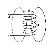
Mutual InductanceAuthor: E.E. Kimberly In Fig. 5-1 is shown a coil A with self-inductance LA carrying an alternating current I which produces a flux θ. All of the flux is assumed to link all the turns N1. If a second coil B with N2( = N1) turns is wound very closely over coil A so that all of the flux θ links also all turns of coil B, then the voltages eA and eB generated in the two coils by the flux θ will be equal. The coils are mutually linked by the same flux and are said to be mutually coupled. Inasmuch as the flux linkages per ampere are the same in both coils, their inductances are the same. However, the inductance of coil B is not a self-inductance because the flux θ which generates the voltage eB in coil B is not produced by current in coil B. That type of inductance is called mutual inductance, to distinguish it from self-inductance, and its symbol is M.
If coil B instead of coil A carried the current, all flux linkages would be the same as when coil A carried the current. Therefore, M is the symbol for the coefficient of flux interaction between mutually coupled coils and the following relations may be written:
and where eA and iA are associated with coil A; eB and IB are associated with coil B; and M is the coefficient of mutual inductance.
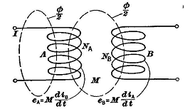
If, as in Fig. 5-2, coil B with N2( = N1) turns is not intimately coupled with coil A but is located so that only half of the flux θ
of to links it, then the mutual inductance is only half as much as in Fig. 5-1 and only half as much voltage is generated in coil B because of iA The effectiveness of coupling is then only half as great because half of the flux θ has leaked through paths that do not pass through coil B, When the coils are intimately associated, the leakage does not exist, the coupling is perfect, and the coefficient of coupling KL is unity. Hence,
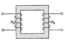
where LA and LB are the coefficients of self-inductance of coils A and B, respectively. The coefficient KL expressed as a fraction simply shows how much of the flux θ produced by coil A is intercepted by coil B. The coefficient of coupling can be varied by moving coil B nearer to or farther from coil A, by rotating the axis of either coil with respect to the other, or by introducing in their mutual path some magnetic material, such as iron, which will increase the flux in that path. Fig. 5-3 shows two coils with a linking iron path which improves the coupling coefficient of the two coils. Mutual-inductance devices are very useful ones, and those called static transformers are discussed in Chapter 17.
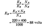
Example 5-2. - A coil A has a self-inductance LI = 220 Solution. - If KL - 1, the voltage generated per turn in coil B would be equal to that in coil A. For this condition, and
Since coil B has only 25 volt sgenerated in it. Then,
|
|||||||
| Home Circuits With Resistance, Inductance, and Capacitance Mutual Inductance |
|
||||||
 10-4 henry and has NA = 1000 turns. Coil B has a self-inductance of 95