| Electrical Engineering is a free introductory textbook to the basics of electrical engineering. See the editorial for more information.... |
|
Home  Circuits With Resistance, Inductance, and Capacitance Power in a Circuit With Resistance and Inductance Circuits With Resistance, Inductance, and Capacitance Power in a Circuit With Resistance and Inductance |
|||||||


|
  |
||||||
|
Power in a Circuit With Resistance and InductanceAuthor: E.E. Kimberly In Fig. 5-22 are shown in sinusoids the conditions in Example 5-3. In such a case the instantaneous product of v and i is not always positive. The part of the power wave below the axis is negative; therefore, the energy represented by the shaded areas is negative energy, that is, flowing from the circuit back into the line. The net energy converted, per cycle, into heat in the circuit is then proportional to the area above the axis less the area below the axis.
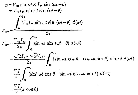
In Fig. 5-22 the power wave completes one cycle of 2π radians in going from a to b, and the power may be expressed as
The vectors of Fig. 5-23 show V and I and their relationship. It may be said that the power is equal to the product of the voltage vector and the projection of the current vector on it. The projection is Icosθ. The product of V and I then is not equal to the power in a circuit with inductance or capacitance; and equation (5-18), or P = VI, is a special case in which cosθ=1. Thus, cosθ is a factor by which the product VI of a circuit must be multiplied to obtain the true power, and this factor is called the power factor. The theory applied here in the inductive circuit applies to capacitive circuits as well.
In Example 5-10, cos(3°45') is the power factor. The following terms are used to identify the various power components:
|
|||||||
| Home Circuits With Resistance, Inductance, and Capacitance Power in a Circuit With Resistance and Inductance |
|
||||||