| Electrical Engineering is a free introductory textbook to the basics of electrical engineering. See the editorial for more information.... |
|
Home  Polyphase Circuits Interpretation of Wattmeter Readings Polyphase Circuits Interpretation of Wattmeter Readings |
|||||


|
  |
||||
|
Interpretation of Wattmeter Readings in Two-Wattmeter MethodAuthor: E.E. Kimberly If θ in Fig. 9-7 were greater than 60°, then the angle (30°+θ) would be greater than 90° and its cosine would be negative. Hence, the reading of wattmeter Wa would be negative and the power Pa would be negative. It should be noted that, for all cases when the current is lagging arid when θ is greater than 0° and less than 90°, Wb will give a higher reading than Wa. If the currents were leading - rather than lagging - their respective phase voltages, Wa would be greater than Wb for values of θ between 0° and 90°. A good method of determining whether the low meter reading on a balanced load should be taken as positive or negative is as follows: From the common line (at C, Fig. 9-6) remove the potential coil wire of the lower-reading wattmeter and touch it on the line containing the other wattmeter. If, then, the needle of the lower-reading wattmeter reverses, the reading is to be taken as negative. If the needle does not reverse, then the reading is to be taken as positive. Return the moved wire to its original position.
Example 9-2. - The meters in the line to a three-phase motor being tested indicate the following values:
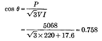
What are the power and the power factor? Solution. - The power is
The power factor is, by equation (9-4),
Thus, Power factor = 75.8%
The power factor for a balanced load may also be found from the equation
Example 9-3. - Calculate the readings of wattmeters W1 and W3 in Fig. 9-4 (a) and the total power.
First Solution. - The wattmeter readings are: The total power is As a check,
Second Solution. - In the calculation of power in problems of this type, when the actual values of line currents are not needed, some students run less risk of error in sign or position of current components if the power indicated by each meter is computed on a different reference axis, instead of being computed on one common axis. For example, the reading of wattmeter W1 in Fig. 9-4 is the product of V21 (the voltage on the potential coil) and I1 cos α, where α is the angular displacement of I1 from V21. There is an advantage, therefore, in taking the x axis of reference through V21 and also in rotating the vector diagram so that V21 is horizontal and runs from left to right as viewed by the student. The diagram will then appear as in Fig. 9-8. To solve for the reading of wattmeter W3 the diagram would be used as in Fig. 9-4, with V23 along the x axis of reference. The simplified vector diagram for computing the reading of W3 is shown in Fig. 9-9. With the axis taken through V21, as in Fig. 9-8, the reading of wattmeter W1 can be found by computing only the in-phase or cosine components of current and then multiplying their sum by V21.
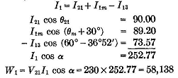
To calculate the reading of wattmeter W3j the work follows:
It is important to note that the reading of the wattmeter W3 is positive because its potential coil is connected across lines 3 and 2 in such a way that the vector - V32 is used in the vector diagram. It must also be recognized that wattmeters W1 and W3 do not actually measure power, but produce two readings which, when added algebraically, give a sum which is equal to the power. The mathematical proof of this fact is given here.
|
|||||
| Home Polyphase Circuits Interpretation of Wattmeter Readings |
|
||||