| Electrical Engineering is a free introductory textbook to the basics of electrical engineering. See the editorial for more information.... |
|
Home  The Direct-Current Machine Lap Winding The Direct-Current Machine Lap Winding |
|||||
| See also: Wave Winding, Stabilizing Windings, Compensating Windings | |||||


|
  |
||||
|
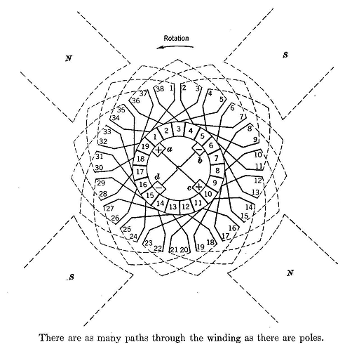
Lap WindingAuthor: E.E. Kimberly The winding in Fig. 10-6 is completely closed with all conductors in series, as in the Δ connection described on page 90. In this case of many conductors distributed around the periphery of the armature, it may be shown that, as in the Δ connection, the instantaneous algebraic sum of all emf's is zero. Hence, no current will flow around the winding. By Fleming's right-hand rule, the emf generated in each conductor under a south pole will be down, while the ernf in any conductor under a north pole will be up. Brush, a is said to be positive because current would leave the commutator at that point if an external circuit were available.
Similarly, it may be shown that brush c is positive and at the same potential as brush a. Brushes a and c may be connected together and be used as the positive terminal of the generator. Brushes b and d are negative and may likewise be connected together to form the negative terminal of the generator. The poles alternate in polarity in sequence around the armature, and the brushes likewise alternate in sign around the commutator. If the winding in Fig. 10-6 is followed, it will be seen that the path laps back upon itself repeatedly. The armature is therefore said to be lap wound. Fig. 10-7 shows a resistive circuit equivalent to that of a lap-wound armature for a four-pole generator. Each brush must be wide enough to make contact with at least two segments at all times. Therefore, at least one coil is always short-circuited by every brush. These coils are said to be under commutation because, when the generator is loaded, the current in them is reversed in the interpolar spaces. The brushes are always so placed that the conductors of the commutated coil are in the interpolar regions. They therefore cut no main pole flux and generate no emf, except as described under the subject of interpoles. Conductors under commutation contribute nothing to the generator's terminal voltage. Fig. 10-10 is a developed lap winding of a four-pole generator with 25 armature slots.
|
|||||
| Home The Direct-Current Machine Lap Winding |
|
||||