| Electrical Engineering is a free introductory textbook to the basics of electrical engineering. See the editorial for more information.... |
|
Home  The Direct-Current Machine Wave Winding The Direct-Current Machine Wave Winding |
|||||||||||||
| See also: Lap Winding, Stabilizing Windings, Compensating Windings | |||||||||||||


|
  |
||||||||||||
|
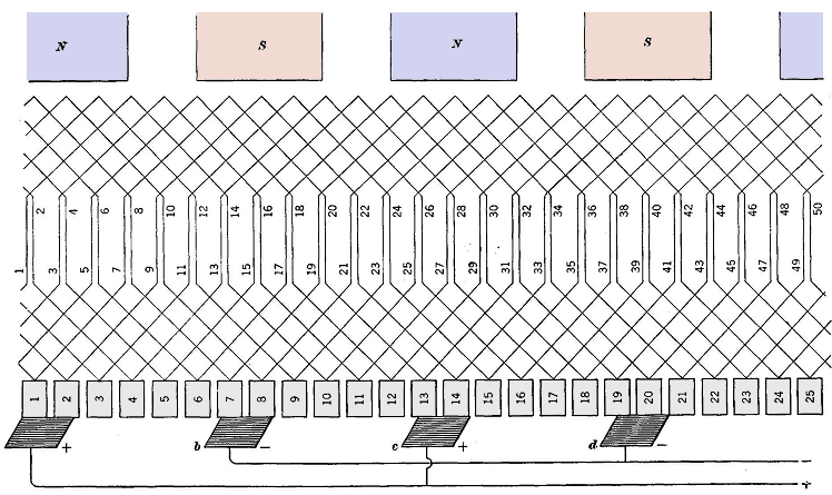
Wave WindingAuthor: E.E. Kimberly In Fig. 10-8 is shown another type of winding on an armature core similar to that of Fig. 10-6. This winding proceeds in the same direction many times around the armature and closes on itself. This type of winding is called a wave winding. In Fig. 10-9 is shown a resistive circuit equivalent to that of a wave-wound armature for a four-pole generator. Fig. 10-11 shows a developed wave winding on an armature similar to that used in Fig. 10-10. The designer's choice between the wave winding and the lap winding is determined by the voltage, speed, and kilowatt capacity of the generator. For a given speed, number of poles, and number of armature conductors, the wave winding gives a higher voltage than a lap winding for the following reason: In a wave winding (simplex)1 half of the conductors are in series between brushes, whereas in a lap winding (simplex) the number of conductors in series between brushes is equal to the total number of conductors divided by the number of poles. In a lap-wound armature, two paths in parallel deliver current to each positive brush. There are as many brushes as there are poles, and so a lap winding always has as many paths in parallel as there are poles. With a wave-wound armature there are usually as many brushes as there are poles, although there are only two paths through the armature irrespective of the number of poles. Inspection of Fig. 10-8 will verify the foregoing
statement for the four-pole generator. In Fig. 10-8 segment 5 touching negative brush b is directly connected to segment 14 touching negative brush d through conductors 9 and 16. The coil 9-16 is then under commutation at the point shown and is contributing nothing to the generator's terminal voltage.
|
|||||||||||||
| Home The Direct-Current Machine Wave Winding |
|
||||||||||||