| Electrical Engineering is a free introductory textbook to the basics of electrical engineering. See the editorial for more information.... |
|
Home  Control of Direct-Current Motors Series-Relay Starters Control of Direct-Current Motors Series-Relay Starters |
|||


|
  |
||
|
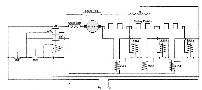
Series-Relay StartersAuthor: E.E. Kimberly As a motor accelerates, its counter emf increases and causes the armature current to decrease. In Fig. 15-7 is shown the wiring diagram of a series-relay type of starter which depends on decreasing armature current for its operation.
When the starting button is pushed, the relay SC closes its contacts. Contacts M close the armature circuit and cause the motor to start. Contacts HC are holding contacts which short-circuit the starting-button contacts. Contacts CC close the circuit on one side of the coils of relays C1A, C2A, and C3A. Relays C1A, C2A, and C3A are high-inductance relays, which act slowly; and so the quick-acting relay SRI in series with the armature opens its contacts before relay C1A can close. As the motor accelerates, its armature current decreases to the point at which relay SR1 is no longer held open and its contacts close and energize C1A, Relay C1A closes its contacts and thereby short-circuits SR1 and also the first section of the starting resistor. The whole armature current then flows in SR2 and causes it to open its contacts before slow-acting relay C2A can act. The initial inrush of current in SR2 then subsides as the motor further accelerates, until the armature current is no longer large enough to hold SR2 closed. This performance is repeated by the other relays, SR3, C2A, and C3A, until all of the starting resistance has been short-circuited and the motor is connected directly to the line. The closure of the contacts of relays ClA C2A, and C3A is firm, and the danger of contact welding is much less than it is with the counter-emf type of starter. The series-relay type of starter has the disadvantage of having a multitude of relays, which require an unusual amount of attention in their maintenance.
|
|||
| Home Control of Direct-Current Motors Series-Relay Starters |
|
||