| Electrical Engineering is a free introductory textbook to the basics of electrical engineering. See the editorial for more information.... |
|
Home  Control of Direct-Current Motors Series-Lockout Starters Control of Direct-Current Motors Series-Lockout Starters |
|||


|
  |
||
|
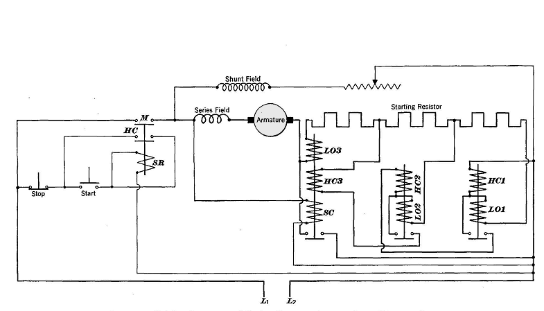
Series-Lockout StartersAuthor: E.E. Kimberly Some of the undesirable features of the series-relay type of starter are avoided in the series-lockout type shown by diagram in Fig. 15-8. This type of starter makes use of a special type of relay containing two coils in series. Each coil is on a separate magnetic frame and produces a separate magnet. One magnet used, as HC1, HC2, or HC3 of Fig. 15-8, is called the holding magnet; and, when energized, it acts to close the relay contacts. The other magnet used, as L01, L02, or L03, is called the lockout magnet, and acts simultaneously to open the relay contacts. The holding magnet is designed for high magnetic leakage and is magnetized by the armature current to a point high above the knee on its magnetization curve. The lockout magnet is designed so as to provide a large air-gap in its magnetic circuit. It is magnetized by the motor inrush current only to a point just below the knee on its magnetization curve. When the magnets are magnetized simultaneously by the motor inrush current, the lockout magnet is the stronger of the two; and the contacts are held open, and all of the starting resistor is left in the circuit. As the inrush current decreases, the lockout magnet loses strength more rapidly than does the holding magnet, until a current value is reached at which the holding (closing) magnet strength predominates and closes the relay contacts.
When the starting button is pushed, the starting relay SR in Fig. 158-closes the main motor contact switch M and also the usual holding contacts HC. The starting inrush current flows through LOS, the starting resistor, L01, and HCl. When the starting current has decreased sufficiently, HC1 closes the relay contacts and almost completely short-circuits the first section of the starting resistor. The armature current then flows through L03, two-thirds of the starting resistor, L02, HC2, and HCl. When the inrush current decreases again sufficiently, HC2 closes its relay contacts. The cycle is repeated by LOS and HC3. When HC3 closes its contacts, all series coils are de-energized and the HC3 contacts are held closed by a small shunt coil SC. The series-lockout starter is simpler than the series-relay starter and requires no interlock relays or fingers. The series-lockout type of starter is not well adapted to the control of variable-speed motors.
|
|||
| Home Control of Direct-Current Motors Series-Lockout Starters |
|
||