| Electrical Engineering is a free introductory textbook to the basics of electrical engineering. See the editorial for more information.... |
|
Home  Control of Direct-Current Motors Definite-Time-Interval Starters Control of Direct-Current Motors Definite-Time-Interval Starters |
|||


|
  |
||
|
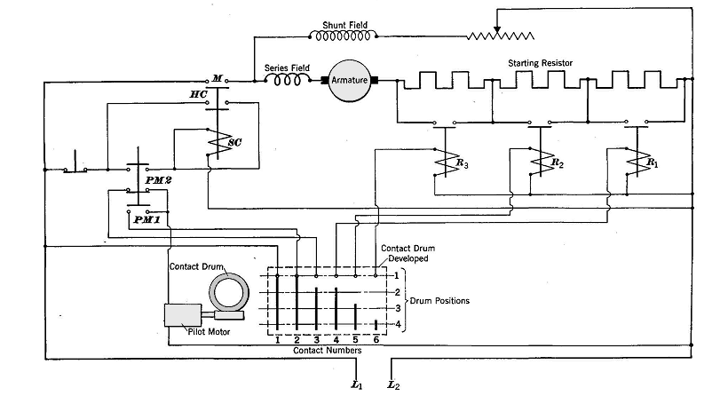
Definite-Time-Interval StartersAuthor: E.E. Kimberly The three types of automatic motor starters previously described have one common fault under some starting conditions. If the motor should fail to accelerate at any point in the sequence of starting because of overload or because of low line voltage, the changes in voltage or in current which initiate the successive steps of operation of the starter would not take place and the starting cycle would not be completed. In the definite-time-interval starter, the time-delay between the successive closings of the contactors which short-circuit the starting-resistor sections is a fixed interval, regardless of the magnitude of current or of voltage changes in the motor. In Fig. 15-9 is shown a wiring diagram of a definite-time-delay (interval) starter. This type of starter will cause a motor to accelerate to its proper speed or to be disconnected from the power line by overload protective devices. When the starter button is pushed, the relay SC closes its contacts. Contacts M close the armature circuit and cause the motor to start. Contacts HC are the usual holding contacts which short-circuit the starting-button contacts. At the same time, contacts PM1 close and start the pilot motor, which rotates the contact drum slowly away from position 1 toward position 2. In position 2, contact 3 closes and energizes relay R1, which short-circuits the first one-third of the starting resistor. In positions 3 and 4 of the contact drum, relays R2 and R3 are caused to short-circuit the remaining sections of the starting resistor. The pilot motor is stopped by the opening of its circuit in drum position 1. Automatic starters of this type are suited to applications in which more than one motor is to be started at the same time. Corresponding additional contact fingers and starting resistors must be provided on the contact drum when multiple starting must be accomplished.
|
|||
| Home Control of Direct-Current Motors Definite-Time-Interval Starters |
|
||