| Electrical Engineering is a free introductory textbook to the basics of electrical engineering. See the editorial for more information.... |
|
Home  Transformers Construction Transformers Construction |
|||||


|
  |
||||
|
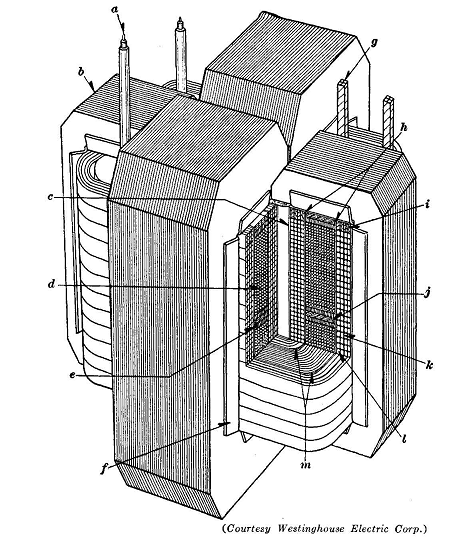
ConstructionAuthor: E.E. Kimberly A common type of magnetic circuit for a transformer is shown in Fig. 17-4. If the primary and secondary coils are Interleaved" or assembled very closely together, the leakage flux between coils and the voltage regulation are reduced to a minimum. Transformers designed for arc-furnace service are purposely arranged for high flux leakage, in order to produce large voltage regulation and thus protect the connected power line from excessive voltage disturbances when the arcs are struck.
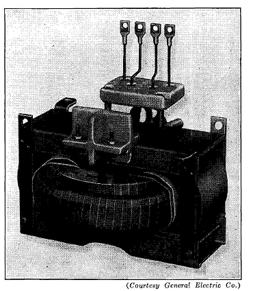
Fig. 17-5 shows another type of core and coil assembly in which the primary and secondary coils are form-wound and are nested together before the iron core is added. The core is in two parts, each consisting of a coil of core steel wound around one side of the O-shaped coil assembly. This construction has several advantages compared to the construction using punchings. The magnetic flux is carried in a path in which the grain direction in the iron is parallel to the flux direction and the maximum permeability of the iron is therefore utilized. The air-gap reluctance is a minimum because the flux in its whole path crosses but one gap; and that gap is only as long as the distance between adjacent convolutions of the iron strip, and its area is equal to that of one side of the strip. The weight is less than with older types of construction and, because the core can be applied by a special machine, the cost and the selling price are advantageous.
|
|||||
| Home Transformers Construction |
|
||||