| Electrical Engineering is a free introductory textbook to the basics of electrical engineering. See the editorial for more information.... |
|
Home  Transformers Vector Diagrams and Voltage Regulation Transformers Vector Diagrams and Voltage Regulation |
|||||||


|
  |
||||||
|
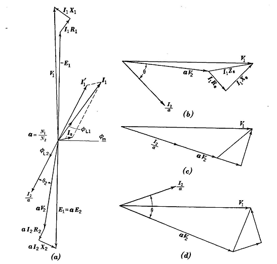
Vector Diagrams and Voltage RegulationAuthor: E.E. Kimberly Fig. 17-3 (a) is the vector diagram of an actual transformer and shows how the leakage impedances exact their vectorial toll of the voltage and leave only a substantial residue which varies with change in either the power factor or the current in the load. The secondary vectors are drawn to the same scales as the primary ones and are then multiplied by the turns ratio
The exciting current Ie which produces the flux ϕm would be in phase with ϕm if there were no copper or iron losses. The flux ϕm generates the electromotive force E1 in the primary coil and E2 in the secondary coil. The voltage E2 forces current I2 through the secondary leakage impedance E2 +jX2 and the load impedance. The current I'1 is the added or "cancellation" current that appears in the primary coil to balance the magnetomotive force mmF2 caused by N2I2. The total primary current I1 causes an impedance drop I1(R1+jX1) in the Primary coil. Voltage V1 then has a component - E1 to balance E1 and another to provide the primary voltage drop I1Z1.
The secondary generated voltage aE2 then fails to equal V1 because of the combined effect of both primary and secondary impedances. The impedances Z1 and Z2 may be combined to make a total effective impedance Ze. Thus, or
a High-Voltage Leads 6 Distributed Shell Form of Magnetic Circuit c Barrier Between Coils and Iron d High-Voltage Windings of Cotton-Covered Enameled Copper Wire e Layer Material of Micarta Paper Crimped at Ends f Fullerboard Channels Between Coils and Iron g Low-Voltage Leads h Barrier Between High-Voltage and Low-Voltage Coils i Fullerboard Collars to Provide Creepage Distance and Give Mechanical Strength j Fullerboard Washers k Cloth Insulation Between Coil Sections I Low-Voltage Winding of Copper Ribbon Insulated With Paper and Cambric Covering m Cooling-Oil Ducts where Ze is the effective transformer impedance of the equivalent circuit of Fig. 17-3 (b) exclusive of the exciting admittance Y which is negligibly small. The voltage regulation of the transformer, in per cent, is
In Fig. 17-3 (b), (c), and (d) are shown equivalent circuit vector diagrams drawn for constant values of V1 and I2 but for three different load power factors, to show how the secondary terminal voltage is dependent on the power factor of the load as well as on the magnitude of I2.
|
|||||||
| Home Transformers Vector Diagrams and Voltage Regulation |
|
||||||