| Electrical Engineering is a free introductory textbook to the basics of electrical engineering. See the editorial for more information.... |
|
Home  Transformers Auto-Transformers Transformers Auto-Transformers |
|||||||


|
  |
||||||
|
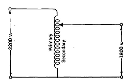
Auto-TransformersAuthor: E.E. Kimberly An auto-transformer has but one winding from which two or more tap leads are made available, as in Fig. 17-14. It is not economically adapted to high-ratio transformation, and the voltage difference between the high-voltage and low-voltage sides seldom exceeds 50 per cent of the higher value. Auto-transformers are commonly used in thermionic battery-charging circuits and transformer-type starters for induction and synchronous motors. The secondary circuit is not insulated from the primary circuit, as in the two-winding transformer, and the auto-transformer is therefore dangerous to life for some purposes.
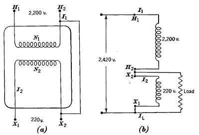
If the losses in an auto-transformer are ignored, it may be said that the volt-amperes input is equal to the volt-amperes output. An ordinary two-winding transformer, such as the one shown in Fig. 17-6 with a permanent connector as in Fig. 17-15 (a), may be used as a step-up or step-down auto-transformer. By connecting terminals H1 and H2 to a 2200- volt line, 2420 volts may be obtained at terminals H1 and X1. Also, by connecting terminals X2 and X1 to a 220-volt line, 2420 volts may again be obtained from terminals H1 and X1.
It should be noted that, when the secondary is loaded as in the simplified diagram of Fig. 17-15 (b), part of the load current comes to the load "conductively" from the line downward toward the load tap. The remainder of the load current comes to the load "inductively" from the secondary coil upward toward the load tap. Ihe portion
and
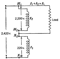
Example 17-3. - If the transformer of Fig. 17-16 is rated 100 kv-a as a two-winding transformer, how many amperes may be delivered to a 2200-volt load connected to terminals H2 and H1 without overloading either winding when the applied voltage at H1 and X1 is 2420?
Solution. - In a two-winding transformer the full-load current of the 2200-volt winding is
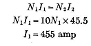
This then is the maximum permissible value of I2. Hence, or and
Also,
With this loading, neither the primary nor the secondary winding is overloaded
|
|||||||
| Home Transformers Auto-Transformers |
|
||||||