| Electrical Engineering is a free introductory textbook to the basics of electrical engineering. See the editorial for more information.... |
|
Home  Alternating-Current Generators Effects of Armature Reaction Alternating-Current Generators Effects of Armature Reaction |
|||


|
  |
||
|
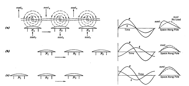
Effects of Armature ReactionAuthor: E.E. Kimberly It may be somewhat surprising to learn that a load that draws leading vars from a synchronous generator may cause the terminal voltage to be greater than the voltage without load. It is evident that a magnetizing effect is being produced in the generator by something other than the mmf of the direct-current winding. That other source is the mmf of the armature reaction. As the term armature is used here, it means the part of the generator that contains the polyphase winding. In Fig. 20-5 is shown one phase of a three-phase generator on a developed diagram with rotor poles. When the rotor poles are in the position in (a) with respect to the stator coil sides, the voltage generated in the phase is of maximum magnitude. If the load is purely resistive, the current will also be at maximum value at the instant shown in (a). The current in the stator winding will produce the magnetomotive force mmfs in the directions shown. The direct current in the windings on the field poles will produce the magnetomotive force mmfr in the directions shown. Examination of the diagram in (a) shows that on every pole one half of the pole has applied to it a resultant mmf equal to mmfr + mmfa and the other half has applied to it a resultant mmf equal to mmfr - mmfs.
The result is a distorted mmf pattern across the pole. Half of the pole will be over-saturated , and half will be under-saturated. Because of the saturation characteristics of iron, more flux will be lost on the weakened side of the pole than is gained on the strengthened side. The machine then incurs a net loss of flux, and the terminal voltage will be less because of that action. This is one cause of loss of terminal voltage when the generator supplies a load with unity power factor. If the load were entirely inductive, as in Fig. 20-5 (b), the current would be at its maximum value 90 electrical degrees later than the instant at which the voltage is maximum. In that time lapse the poles would have moved 90 electrical degrees-from their positions in (a) and would be in direct line with mmfs, the direction of which is opposite to that of mmfr. Therefore, the mmf over the whole pole would be equal to mmfr - mmfs, and the generator would suffer a loss of flux. For any load of I amperes of purely inductive load, the terminal voltage of a generator will be less than that for the same current I of resistive load. If the load were purely capacitive, the rotor poles would be in the positions shown in (c), or not yet up to the positions in (a) by 90 electrical degrees. Therefore, the mmf over the whole pole would be equal to mmfr +mmfs and the generator would gain flux and have a terminal voltage probably greater than that at no load. Loads having intermediate power factors would have intermediate effects. If the generator has three phases, the other two phases contribute to the magnetomotive force mmfa shown for one phase and produce a wave of armature reaction mmf that rotates at synchronous speed always in fixed position relative to the rotor poles under any particular condition of shaft load and power factor.
|
|||
| Home Alternating-Current Generators Effects of Armature Reaction |
|
||