| Electrical Engineering is a free introductory textbook to the basics of electrical engineering. See the editorial for more information.... |
|
Home  Alternating-Current Generators Voltage Control of A-C Generators Alternating-Current Generators Voltage Control of A-C Generators |
|||||


|
  |
||||
|
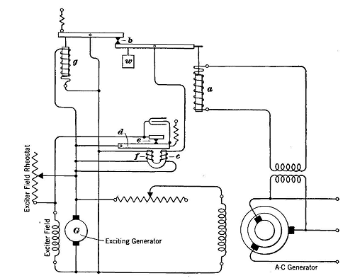
Voltage Control of A-C GeneratorsAuthor: E.E. Kimberly The voltage regulation of alternating-current generators is greater than that of direct-current shunt generators of comparable size. Correction of terminal voltage is usually accomplished by automatic voltage control. A device known as a voltage regulator is commonly used for this purpose. The action of the Tirrill regulator is as follows: In Fig. 20-6 a transformer, with its primary connected across the terminals of the alternator whose voltage is to be regulated, has its secondary connected to a solenoid a. Assume that the alternator voltage is at the desired value and that the regulator parts are therefore at rest. Assume next that additional load is connected to the alternator so that its terminal voltage falls. The decreased pull of solenoid a will permit the weight w to open the contacts b. This action de-energizes coil c and releases the armature dt which closes the contacts at e. These contacts short-circuit the portion of the exciter field rheostat which is in use; and the exciting generator voltage rises and boosts the field of the alternator, so that there is a rise in its terminal voltage. The increased alternator voltage causes solenoid a to be strengthened, and so the contacts at b are closed again. The reclosing of contacts b restores the circuit through coil c, causing the contacts e to open and the exciter field rheostat to be inserted again in the exciter field; and the excitation of the alternator is again decreased. This cycle of events takes place so rapidly that the rise and fall of the alternator voltage back and forth across the normal or average is not perceptible. Coil / is almost, but not quite, strong enough to hold the contacts e open, so that only a small change in current through coil c is required to move armature d. This arrangement increases sensitivity and speed of response. Coil g tends to prevent overshooting of the voltage and to eliminate the action known as "hunting."
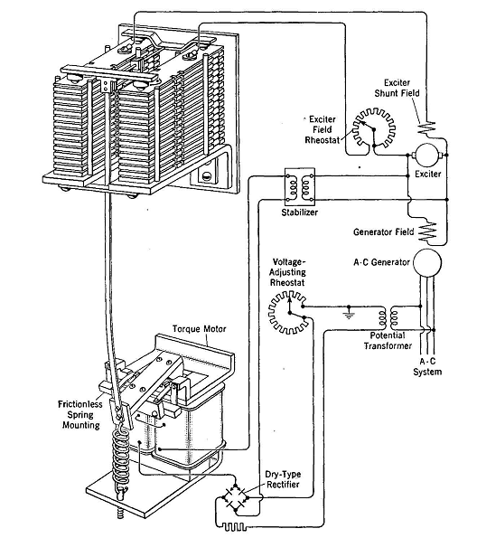
Such a regulator will control the voltage of the a-c generator within close limits, even with large sudden changes in load. It is also possible to cause the terminal voltage to rise with increase in load, so as to compensate for loss of voltage at the load because of impedance voltage drop in the intervening feeders. Fig. 20-7 shows a direct-acting voltage regulator of a simpler type, as built by the General Electric Company. In series with the shunt field of the exciter is a resistance unit consisting of resistance plates in series. The ends of the plates, with contact tips forming a resistance stack, are held together by a spring; and, when not in use; the plates are short circuited and offer no resistance.
When the alternator is started and its voltage approaches the rated voltage, it energizes a torque motor through a potential transformer and rectifier; and the torque motor, acting against the spring of the resistance stack, causes the stack contacts to open one by one and thus inserts added resistance into the exciter field circuit. This action lowers the exciter voltage, and so lowers the generator voltage and thus causes some of the contacts to reclose as the torque motor relaxes. These operations would be repetitive, and the generator voltage would tend to drift or "hunt" above and below the desired normal voltage. To prevent this hunting, a stabilizing transformer is connected across the exciter-armature terminals. As the exciter voltage rises, a voltage is generated in the secondary of the stabilizing transformer. This generated voltage, acting through the rectifier, tends to nullify the rise in voltage on the torque motor and so to stabilize the action and prevent "overshooting"
|
|||||
| Home Alternating-Current Generators Voltage Control of A-C Generators |
|
||||