| Electrical Engineering is a free introductory textbook to the basics of electrical engineering. See the editorial for more information.... |
|
Home  The Single-Phase Motor The Repulsion Motor The Single-Phase Motor The Repulsion Motor |
|||||||


|
  |
||||||
|
The Repulsion MotorAuthor: E.E. Kimberly The repulsion motor has operating characteristics similar to those of the series direct-current motor. It has a stator with a winding similar to that of a split-phase motor without the starting winding.
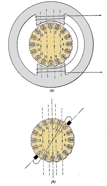
The rotor is similar to the armature of a direct-current motor, but it has no electrical connection to the supply line. The brushes are connected together in a common short-circuit. The principle of operation will be described with the aid of Fig. 21-9. For simplicity the motor is shown with a salient-pole stator and with a rotor having full-pitch winding in which a conductor followed down in any slot would be found to return in a diametrically opposite slot. Consider the rotor to be stationary and the flux to be rising in the direction shown in Fig. 21-9 (a). No flux threads the loop 1-9, and hence no voltage is generated therein. In all other loops, by Faraday's Law, voltages are generated in the directions shown on the respective conductors. If a set of short-circuited brushes be placed on the horizontal axis connecting the winding at the two points 5 and 13, no current will flow because on either the top half or the bottom half the sum of the voltages is zero.
If the brushes be rotated to the vertical axis, a large current will flow in the brushes and in all conductors in the directions shown in (a). By Lenz's Law, conductors 2, 3, 10, and 11 will produce a torque in a counter-clockwise direction, while conductors 7, 8, 15, and 16 will produce an equal torque in a clockwise direction. Hence, the motor will not tend to rotate.
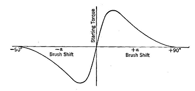
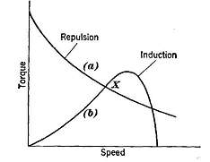
If however, the brushes be rotated through the angle a to the positions shown in Fig. 21-9 (6), a new pattern of currents will appear, as shown. By Lenz's Law, conductors 16, 1, 2, 8, 9, and 10 will produce a clockwise torque without an opposing torque, and the motor will tend to rotate. If the brushes be displaced counter-clockwise from the vertical axis through a similar angle a, the torque will be of the same magnitude as before, but will be in a counter-clockwise direction. The direction of the torque is the same as the direction of brush displacement. Fig. 21-10 shows a typical curve of torque vs. a. The speed-torque characteristic is shown by curve (a) of Fig. 21-11. The repulsion motor is well adapted to small-crane service or other applications in which large starting torque is essential and great speed regulation is not objectionable.
|
|||||||
| Home The Single-Phase Motor The Repulsion Motor |
|
||||||