| Electrical Engineering is a free introductory textbook to the basics of electrical engineering. See the editorial for more information.... |
|
Home  Electronic Devices The Grid-Glow Tube Electronic Devices The Grid-Glow Tube |
|||||||||||


|
  |
||||||||||
|
The Grid-Glow TubeAuthor: E.E. Kimberly
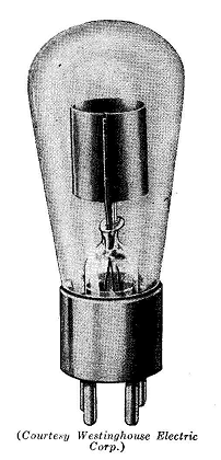
The grid-glow tube, as shown in Fig. 27-27, is a cold-cathode tube with two electrodes and a grid. One of the electrodes is specially designed to act better as a cathode by making it larger than the other and coating it with some substance, such as oxide of barium, strontium, or calcium, to improve its emission. If enough voltage is impressed between the cathode and the plate, with no voltage applied between the cathode and the grid, ionization of the gas will occur and a current will flow. When the tube conducts current in normal operation, all or part of the cathode glows with a pink greenish glow; hence, the name grid-glow is used. If, however, a voltage from battery C in Fig. 27-28 be impressed between the grid and the cathode with the polarity shown, the voltage required of battery B to start the glow and current flow will be changed. If the grid is made positive with respect to the cathode, the breakdown voltage required of battery B will be less. If the grid is made negative with respect to the cathode, the voltage required of battery B for breakdown will be greater.
After conduction through the tube in Fig. 27-28 has started between the cathode and the plate, the grid-cathode voltage is powerless to stop it, and current will continue to flow until the voltage between the plate and the cathode has been reduced below the cut-off voltage of about 50 volts in small tubes and 200 volts in large tubes. Meanwhile, of course, the grid-cathode voltage must have been reduced below the voltage required to start the flow. The grid then regains control, and retains it even though the plate-cathode voltage be raised again.
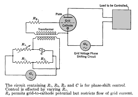
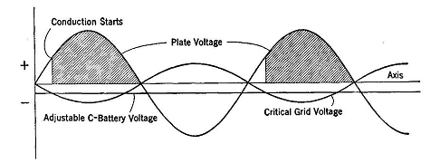
If the B battery of Fig. 27-28 be replaced with a source of alternating voltage, as in Fig. 27-29, the plate voltage will pass through zero twice every cycle, and so the grid voltage may regain control once every cycle. Inasmuch as the tube is not a conductor when the cathode is positive, the plate-current impulses will be in one direction only, and one pulse will occur every cycle, as shown in Fig. 27-30.
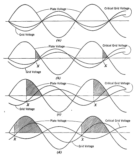
The instant in the plate-voltage cycle at which conduction starts may be adjusted to any point in the first positive quarter of every cycle by adjusting the voltage received on the grid from the battery C. Obviously, the start cannot be delayed to any point in the second quarter of the cycle because all starting values in the second quarter are duplicated in the first. In order to start conduction in the second quarter of the cycle, it is necessary to apply alternating voltage to the grid as well as to the plate. In order to make the starting point adjustable, it is necessary to interpose a phase-shifting network in the grid-voltage circuit, as shown in Fig. 27-29. The critical grid voltage is that minimum grid voltage which will start conduction in the tube for any given plate voltage. If the grid is negative with respect to the cathode, then the critical grid voltage rises as the plate voltage rises. In Fig. 27-31 is shown the effect of phase shift of gild voltage as it controls the time of start of tube conduction in every cycle. As the phase of the grid voltage is shifted, the average value of the current permitted to flow in the plate circuit and load is varied. The grid voltage actually applied has a greater maximum value than the critical grid voltage. voltage exceeds the critical
As long as the grid voltage at all points on the curve, the plate current is blocked. If, however, by a phase-shifting circuit such as shown in Fig. 27-29, the grid voltage be caused to lead in time phase its position shown in Fig. 27-31 (a) and shift to the position in (b), there will be a point X in the plate-voltage cycle at which the critical voltage will be slightly greater than the grid voltage and ionization and hence conduction will occur. After this breakdown, current will flow throughout the remaining portion (shaded in Fig. 27-31) of the positive half of the cycle. Because of the rectifying action previously described, no current will flow during the negative half-cycle. Also none will flow in the following positive half-cycle until the grid voltage again becomes less than the critical voltage. In this manner the effective value of the current permitted to flow in the plate circuit containing the load may be controlled by simply shifting the time phase of the grid potential. The grid-glow tube starts almost instantaneously and requires no heating-up period. It is particularly useful in service where it must be ready for operation without notice and where instant starting is required. It does not deteriorate with age when not operating, and requires no power to keep it at operating temperature. It has a disadvantage, however, in that only a few milliamperes of current may be drawn in its plate circuit. Also, because its gas pressure is high and both electrodes are cold, the voltage at which breakdown will occur in the reverse direction from the anode to the cathode is not much higher than its normal cathode-to-anode breakdown voltage. For this reason, if a grid-glow tube is operated near its peak plate voltage, a momentary small increase in that voltage on alternating voltage may cause the tube to conduct in both directions.
|
|||||||||||
| Home Electronic Devices The Grid-Glow Tube |
|
||||||||||