| Electrical Engineering is a free introductory textbook to the basics of electrical engineering. See the editorial for more information.... |
|
Home  Electronic Devices The Thyratron Electronic Devices The Thyratron |
|||||||||
| See also: The Ignitron | |||||||||


|
  |
||||||||
|
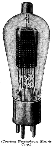
The ThyratronAuthor: E.E. Kimberly The thyratron, shown in Fig. 27-32, is similar in many respects to the grid-glow tube, but its dissimilar characteristics have made it a more generally useful tube. Its higher permissible plate current makes it readily applicable to motor control, welder control, sequence control in manufacturing processes, and innumerable other services. Its cathode is a filament or an electrode heated by radiation from a filament. The tube is filled with a gas, mercury vapor, or a mixture of the two.
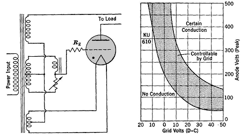
The characteristics of thyratrons are similar to those of grid-glow tubes; but their electron emitters, being heated, will pass much greater current safely. The grid-to-cathode potential difference which will just start ionization depends largely on the voltage applied between the plate and the cathode. In Fig. 27-33 is a typical curve showing the relationship between the plate voltage and the grid-to-cathode potential or "bias." From this curve, for example, it is seen that a plate voltage slightly greater than 60 volts will start ionization and conduction through the tube, if there is no
(Note Dot in Symbol Denoting a Gas or Vapor Tube) grid-to-cathode bias. However, a grid voltage of only 6 volts will prevent ionization at any voltage below 700 volts. The grid voltage is so effective in preventing ionization because the grid is so close to the hot cathode, where the ionizing electrons are emitted. After the grid voltage has triggered the thyratron, the grid is immersed in the avalanche of electrons passing from cathode to anode. The voltage drop between grid and cathode is then very low in that low-resistance path because of the plate current flow and is much lower than existed while the grid was below the triggering potential. To protect the grid circuit against overload current after firing, it is necessary to add a current-limiting resistor Rg in series with the grid. Fig. 27-34 shows a thyratron and its phase-shifting circuit. In conjunction with the symbol for the tube in that circuit, there is shown a dot, which indicates gas in the tube. The effect of grid-voltage phase shift in a thyratron is essentially the same as shown in Fig. 27-31 for a grid-glow tube. Fig. 27-35 shows two thyratrons arranged in a circuit for full-wave rectification.
|
|||||||||
| Home Electronic Devices The Thyratron |
|
||||||||