| Electrical Engineering is a free introductory textbook to the basics of electrical engineering. See the editorial for more information.... |
|
Home  Electronic Applications High-Frequency Oscillators Electronic Applications High-Frequency Oscillators |
|||||


|
  |
||||
|
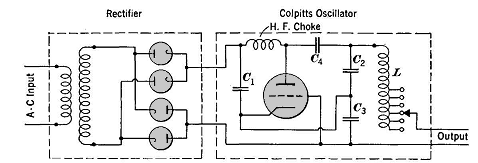
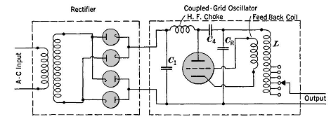
High-Frequency OscillatorsAuthor: E.E. Kimberly High frequencies are here defined as those above 50,000 cycles per second. For industrial power supply the Golpitts circuit, Fig. 28-1, or the coupled-grid self-excited oscillator circuit, Fig. 28-2, is most commonly used. In either circuit, the alternating supply voltage is stepped up through a power transformer to some voltage between about 7500 and 15,000 volts and is then rectified by a suitable bank of mercury-vapor rectifier tubes. In Fig. 28-1 the condensers C2 and C3 form an anti-resonant circuit with L and the inductance of the load which may be an induction heating coil fed at the output terminals. The inductance L is tapped so that, even though different heating coils may be used, the total inductance of the circuit can be kept at proper value for anti-resonance at the desired frequency. Condenser C4 is a "blocking" condenser and prevents the flow of direct current into the resonant circuit. The high-frequency choke coil passes the direct current to the anode of the oscillator tube, but presents a high limiting impedance to the high-frequency currents which would otherwise flow back into the rectifier. The condenser C1 by-passes back to the cathode any high-frequency current which does pass through the choke.
The voltage across condenser C3, being applied between the grid and the cathode of the oscillator tube, feeds back part of the tube's anode output, and so causes the tube to be an amplifier and hence a self-regenerator at the frequency established by the constants of the anti-resonant circuit. The oscillator tube is a high-voltage vacuum tube sometimes known as a pliotron.
In Fig. 28-2 the grid voltage is supplied by a feed-back coil inductively coupled to the variable inductance L. The condenser CR replaces the condensers Cz and C3 of Fig. 28-1.
|
|||||
| Home Electronic Applications High-Frequency Oscillators |
|
||||