| Electrical Engineering is a free introductory textbook to the basics of electrical engineering. See the editorial for more information.... |
|
Home  Electronic Applications Relaxation Oscillators Electronic Applications Relaxation Oscillators |
|||||||||||||||||


|
  |
||||||||||||||||
|
Relaxation OscillatorsAuthor: E.E. Kimberly
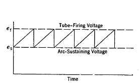
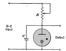
The oscillator known as a relaxation oscillator works on the principle that the rate of charging a condenser from a d-c supply can be controlled by a series resistor, much as the rate of filling a tank with water at constant pressure can be controlled by throttling the discharge pipe. The chief use of this type of oscillator is in the production of periodic voltage pulses which rise from one value to a higher value linearly in time as shown in Fig. 28-3. When voltage is applied to the circuit represented in Fig. 28-4,
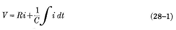
The term
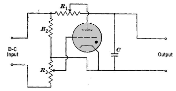
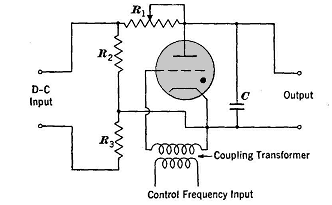
The condenser then proceeds to recharge, and the cycle is repeated. The voltage ec appears at the output terminals, as shown in Fig. 28-4. The lower the resistance R, the faster will the condenser charge, and the faster will the cycle be repeated. Thus, the frequency is readily controlled by adjusting the resistance R. This type of oscillator is used in the cathode-ray oscilloscope to sweep the beam along the reference axis at a constant speed and then to return it very quickly to its starting point for repetition. Another circuit, using a gaseous triode, is shown in Fig. 28-5. Resistors R2 and R3 form a voltage divider by which the grid voltage may be adjusted so that the firing voltage of the tube condenser, and hence of the tube, may be controlled. The frequency of discharge is controlled by the resistance R1.
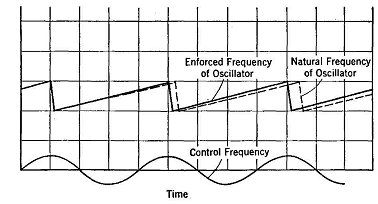
It is sometimes desirable to synchronize exactly the frequency of a relaxation oscillator with that of some other frequency source, such as a 60-cycle power line. This synchronizing may be accomplished by using the circuit of Fig. 28-5 modified as in Fig. 28-6. In operation, the synchronizer acts to fire the tube at one definite point on the control frequency cycle a brief instant before the oscillator condenser alone would have fired it. To accomplish this, the oscillator frequency is adjusted by resistor R1 to a value just below that at which it is to be synchronized, as shown in Fig. 28-7.
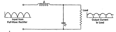
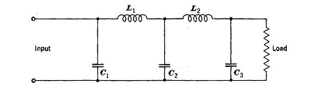
Let it be assumed that, on the first positive half-cycle of control frequency shown, the oscillator tube would have fired at exactly the correct time without grid-voltage urge. On the next positive half-cycle, it would have fired slightly too late without the urge of the grid-control voltage. Every successive cycle of the oscillator then is caused to start at the same instant on its corresp6nding grid-control voltage, and the oscillator-output frequency is the same as the grid-voltage frequency regardless of its tendency to lag. It is obvious that synchronizing cannot occur if the natural oscillator frequency is greater than that desired, because the tube could fire when the necessary plate voltage was reached irrespective of the urge or control by the grid voltage. Cathode-ray oscilloscopes use this method for producing stationary screen patterns. Filter Circuits.The output of a rectifier, as shown in Fig. 27-3, is satisfactory for charging a battery or for operating a relay, but for most purposes it must be smoothed out until practically pure direct current remains with very little "ripple." This smoothing is accomplished by means of filters consisting of networks of R, L, and C circuit components arranged in a unique fashion. Fig. 28-8 shows a very simple filter consisting of one L unit or " choke" and one condenser interposed between the rectifier and the load. For only moderate smoothing of the current, this simple filter may be sufficient; but, for more complete purification of current output, more units must be added as in Fig. 28-9 and Fig. 28-10.
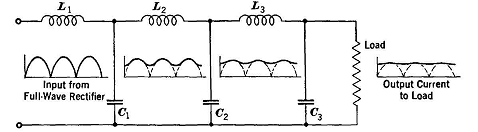
In Fig. 28-9 the current encounters the choke L1 first, and so the filter is called an inductance-input filter. This choke offers high impedance to the high-frequency components of currents and reduces them, but gives the fundamental-frequency and d-c components little opposition. The fundamental component divides; part of it passes on through choke L2 and part of it charges condenser C1. As the component passing through L2 starts to decrease, C1 discharges and tends to maintain the current in L2. Thus, the current in L2 never falls to zero but varies about as shown in the graph at L2. Successive filter units L1C1, L2C2, etc. may be added until the output is sufficiently pure for the purpose intended. In Fig. 28-10 the current encounters the condenser C1 first and the filter is called a condenser-input filter. The filtering action is essentially the same as that in an inductance-input filter. In comparing the two types of filters, it is seen that in the condenser-input filter the last condenser is a reservoir of energy from which load energy may be drawn almost steadily while the replenishment is intermittent. If the load current be increased, it must be drawn at a reduced voltage because the intermittent input increments are not sufficient to maintain the originally higher state of charge. For this reason the condenser-input filter has a poor voltage regulation and is poorly suited for varying load. An inductance-input filter must have a certain minimum current in its inductances to be effective. It therefore follows that with light load the filtering action is less satisfactory than at loads nearer rated load. The voltage regulation of this type of filter is better than that of a condenser-input filter, but the filter should always be at least partly loaded for best results. The inductance-input filter is best suited to varying power loads.
|
|||||||||||||||||
| Home Electronic Applications Relaxation Oscillators |
|
||||||||||||||||