| Electrical Engineering is a free introductory textbook to the basics of electrical engineering. See the editorial for more information.... |
|
Home  Electronic Applications The Cathode-Ray Oscilloscope Electronic Applications The Cathode-Ray Oscilloscope |
|||


|
  |
||
|
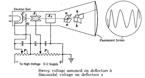
The Cathode-Ray OscilloscopeAuthor: E.E. Kimberly The cathode-ray oscillograph or oscilloscope is a device for observing high-speed phenomena in electrical circuits, and operates very much like the magnetic Duddell type described on page 188. In the cathode-ray type, however, the visible trace is produced on the large end of a funnel-shaped tube, the end of which is coated with a fluorescent material. Fig. 28-23 shows the construction, schematically, of a cathode-ray tube and its accompanying control circuits.
In Fig. 28-23 the electrons are boiled off into a cloud around the cathode C, which is indirectly heated from the filament. High potentials on anodes A1 and A2 accelerate the freed electrons and focus some of them into a thin beam or ray as they pass through the anodes to bombard the fluorescent screen. If deflecting electrodes a and b are not energized, the spot of light on the fluorescent screen caused by the striking of the electron ray will be in the center of the screen. If, however, a saw-toothed voltage function, such as shown in Fig. 28-3, be impressed on deflecting plates b, the beam will be deflected by the electrostatic charge on the plates and will be caused to sweep horizontally at uniform velocity across the screen and then to snap back quickly. The frequency with which the sweeps are repeated is determined by the setting of the relaxation oscillator or an equivalent device. Such a sweep of the spot on the screen provides a time axis on which to superpose the magnitude function of any voltage wave to be investigated as to shape. The voltage to be analyzed is impressed across deflection plates a, which deflect the ray vertically in proportion to the magnitude of the voltage. In Fig. 28-23 is shown a screen trace that would be obtained by energizing deflection plates a by a sinusoidal voltage. It is important to note that the wave trace is accurate only in the center portion of the screen and is distorted on both ends. In order to make use of the full width of the screen, there is usually maintained on the horizontal deflectors a constant voltage called a "pedestal" voltage which is just great enough to deflect the static spot to one side of the screen. In Fig. 28-23 the grid G is used to control the beam or ray density, and hence the brightness of the luminous spot is controlled by changing P1. The structure of the grid and the aperture in anode AI are so designed as to prevent passage of all electrons which tend to stray from the desired beam path. The focusing of the beam is controlled by P2. Most of the electron acceleration is accomplished by the potential on anode A2. Deflection of the beam is sometimes accomplished magnetically instead of electrostatically. Because of greater simplicity in the construction of magnetic-deflection tubes, they are cheaper than electrostatic-deflection tubes. However, the magnetic-deflection principle, because of the lag of current caused by inductance in the coils, is not suitable for voltage measurements, but is confined to the sweep axis. Electrostatic deflection has the advantage that practically no power is required, and the auxiliary circuits are simpler than those required for electromagnetic deflection. The Duddell type of oscillograph is satisfactory for frequencies up to about 5000 cycles per second, but the cathode-ray oscilloscope is applicable to all frequencies up to the high-range radio frequencies at which the time of one cycle is comparable to the transit time of the electron between the cathode and the fluorescent screen. Cathode-ray oscilloscopes are usually equipped with suitable preamplifiers for the deflector circuits, so that input voltages of low magnitude may be analyzed satisfactorily.
|
|||
| Home Electronic Applications The Cathode-Ray Oscilloscope |
|
||