| Capacitors, Magnetic Circuits, and Transformers is a free introductory textbook on the physics of capacitors, coils, and transformers. See the editorial for more information.... |

|
Home  Energy Series R-L-C Circuit Energy Series R-L-C Circuit |
|||||||||||||||||||||||||||||


|
  |
||||||||||||||||||||||||||||
Series R-L-C Circuit
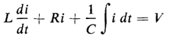
Figure 1-13 shows the schematic diagram of a series R-L-C circuit to which is applied a constant d-c voltage V. In this circuit the applied voltage satisfies the following equation
where L = constant self-inductance in henries
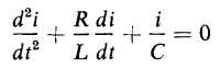
Equation 1-73 is of exactly the same form as Eq. 1-57, which applies to the mechanical system with mass, friction, and elasticity. The integral in the left-hand side of Eq. 1-71 is eliminated by differentiation with respect to time. Hence
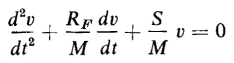
If Eq. 1-58 is divided by M, the result is
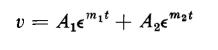
A comparison of Eq. 1-75 with Eq. 1-74 shows these equations to be identical except for the values of the constant coefficients. This comparison then shows that solution of Eq. 1-72 must be of the same form as that of Eq. 1-75, the only difference being in the constant coefficients. The solution of Eq. 1-75 is given by Eq. 1-62 as follows
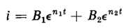
On that basis the solution of Eq. 1-74 is
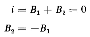
Because of the self-inductance the current must be zero at t = 0, the instant when the d-c voltage is applied; so from this boundary condition when t = 0, then i = 0, and
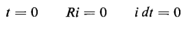
Equation 1-76 establishes the relationship between the unknown constants B1 and B2 but does not evaluate them in terms of known constants. Either of these constants, B1 or B2 can now be evaluated, however, in terms of the known constants R, L, and C and the applied voltage V for the same boundary condition as follows. The current is zero at t = 0. This means that the term Ri in Eq. 1-73 must be zero at t = 0 also. Furthermore, since at t = 0 no current has as yet been applied to the capacitor, the time integral of the current must also equal zero. Substitution of
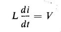
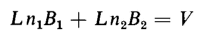
in Eq. 1-71 yields
and
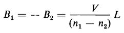
From Eqs. 1-77 and 1-78 there results
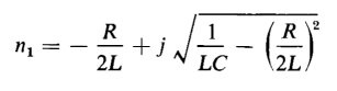
The process involved in the solution of Eqs. 1-58, 1-59, and 1-60 when applied to this case yields
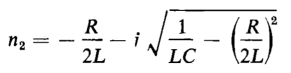
and
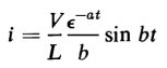
Equations 1-79 and 1-80, when substituted in Eq. 1-76 yield
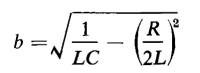
where a = R/2L and
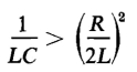
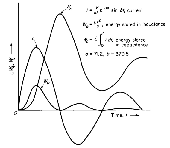
From Eq. 1-81 it is evident that the current i may undergo two different kinds of variation with respect to time. The current may (1) oscillate or it may (2) rise to a maximum and then gradually die out without reversing its direction. Current oscillatory When the constant b in Eq. 1-81 is real, i.e., if
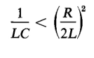
the current i oscillates, its successive amplitudes decreasing at a rate determined by the constant a. The current and energy relationships of a series R-L-C circuit are shown graphically as functions of time in Fig. 1-14. When the current in Fig. 1-14 is positive the circuit absorbs energy from the source of voltage and when the current is negative the circuit returns energy to the source. If all of the energy in the circuit were reversible, i.e., if there were no heat losses, the negative current peaks would equal the positive current peaks and the circuit would return as much energy to the source when the current is negative as it received during the half cycle when the current was positive. To satisfy the condition of no heat losses the resistance R of the circuit must be zero. When R = 0, the constant a in Eq. 1-81 is also zero, and the equation then defines a steady alternating current. Current nonoscillatory When the constant b in Eq. 1-81 is imaginary, i.e., if
then the trigonometric sine in Eq. 1-81 becomes a hyperbolic sine and the current flows in one direction only, building up to a maximum value and then gradually dying out as the capacitor becomes charged to a potential difference that approaches the value of the applied voltage V. This is a case in which the reversible energy is so great in relation to the energy stored in the self-inductance L and in the capacitance C that there is no energy returned to the source while the capacitor is charged.
The case that serves as a dividing line between an oscillating current and a nonoscillating current is a critically damped circuit where the constant b = 0, i.e.
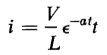
If b is made zero in Eq. 1-81 the right-hand side of that equation becomes an indeterminate that can be evaluated on the basis that
Substitution of Eq. 1-80 in Eq. 1-79 yields
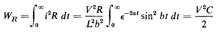
Whether the current oscillates or not, the irreversible energy, i.e., the energy converted into heat is expressed by
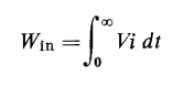
The total energy input to the circuit is
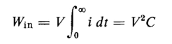
and since the applied voltage V is a constant it can be taken outside the integral, thus
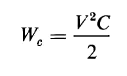
The final voltage across the capacitor determines the final energy stored in the capacitor and, in this case, this final value of voltage is the constant applied voltage V. The final energy stored in the capacitor is therefore given by Eq. 1-55 as
It therefore follows that, with a constant applied d-c voltage, the irreversible energy in the series R-L-C circuit equals the stored energy so that, in this case also, one-half of the energy input is irreversible. Since Eq. 1-67 for the case of the mechanical system is similar to Eq. 1-81, it follows that conditions analogous to the cases of the oscillating and non-oscillating current must exist. Thus, if in Eq. 1-67 the constant b is real, the motion of the mass M reverses its direction periodically, and the mass gradually comes to rest. If on the other hand the constant b is imaginary, the mass M moves only in the direction of the applied force F, and gradually comes to rest without any reversal in the direction of motion. It is significant that when a constant force is applied to a system in which the energy is finally stored in the deformation of a body such as a spring, one-half of the energy input to the system is converted into heat. This is true also in the case of an electric circuit in which the energy is finally stored in an ideal capacitor. Thus, under the condition of a constant applied force, a spring is capable of storing, at best, only 50 percent of the applied energy in reversible form. This is also true of a capacitor under the condition of constant applied voltage.
|
|||||||||||||||||||||||||||||
| Home Energy Series R-L-C Circuit |
|
||||||||||||||||||||||||||||


Last Update: 2011-01-04